Self-diagnosis and sequential-display method of every function

Inactive Publication Date: 2008-08-21
LEE SANG SU
View PDF3 Cites 2 Cited by
  • Summary
  • Abstract
  • Description
  • Claims
  • Application Information

AI Technical Summary

Problems solved by technology

Therefore, there are many difficulties in the test of products under the manufacturing process since each function key must be individually manipulated.

Method used


Image

  • Self-diagnosis and sequential-display method of every function
  • Self-diagnosis and sequential-display method of every function
  • Self-diagnosis and sequential-display method of every function

Examples


Embodiment Construction

[0009]The present invention will now be described in more detail with reference to the accompanying drawings.

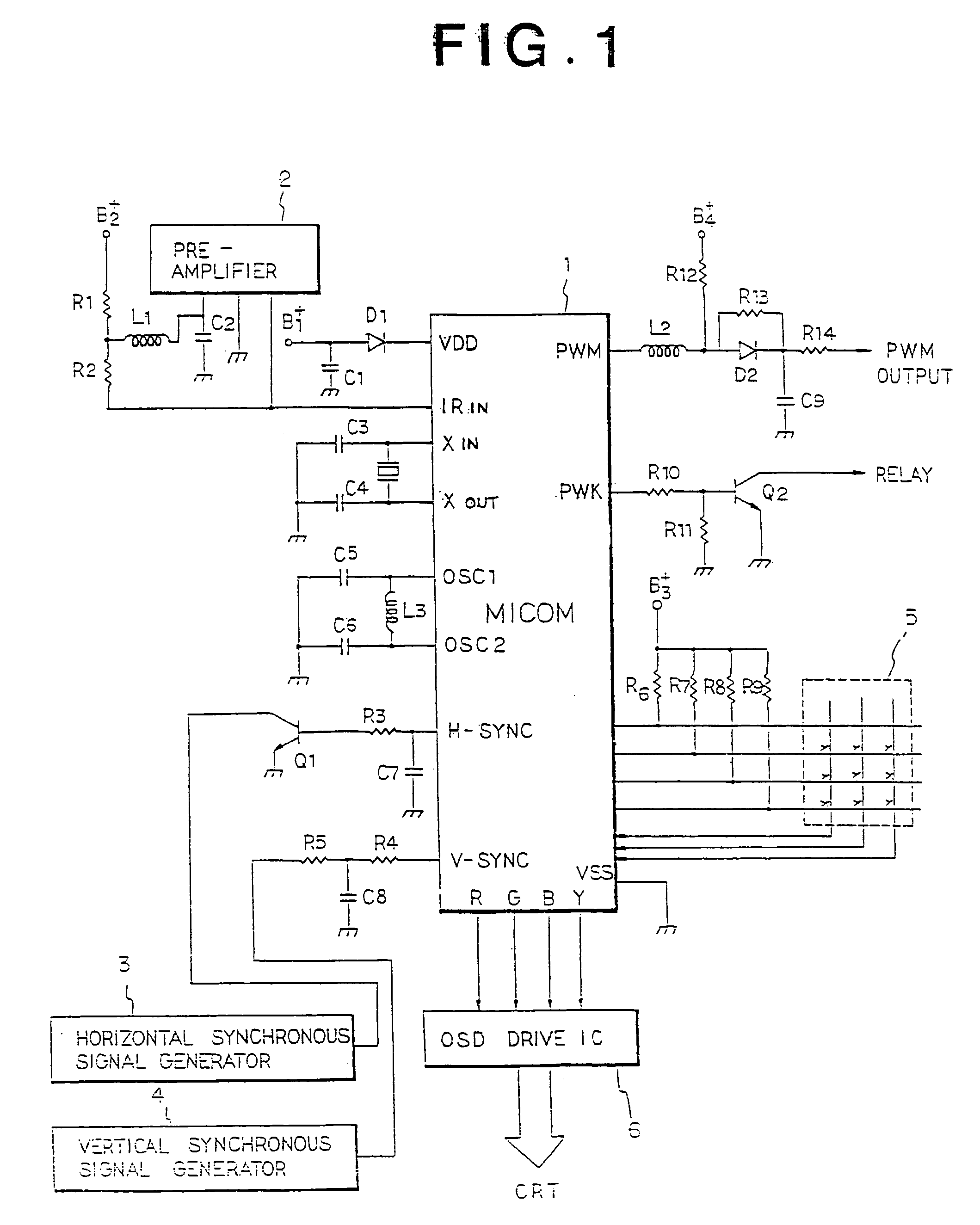
[0010]As an embodiment of the present invention, general functions which are applicable to a television are chosen and a circuit around a MICOM 1 inside the television is shown in FIG. 1. When a power VDD and a clock signal are applied to the MICOM 1, a transmitted signal from a remote controller is amplified by a pre-amplifier 2 and is subsequently applied to the MICOM 1.

[0011]Also, horizontal and vertical synchronous signals for on-screen display (OSD), which are respectively generated from horizontal and vertical synchronous signal generators 3 and 1, are applied to the MICOM 1. In addition, a key matrix 5 is connected to the MICOM 1 and thus the MICOM 1 recognizes the function key of MICOM 1 or the remote controller to display OSD characters on cathode ray tube (CRT) by driving an OSD drive integrated circuit (IC) 6.

[0012]The MICOM 1 turns on / off the main power by control...


PUM


Abstract

The present invention related to an automatic machine, which performs automatically self-diagnosis and demonstration of functions without individual manipulations of every function by informing the consumer operation states of selected functions after displaying sequentially menu screens with executing a subroutine stored in a microcomputer according to an entrance of a demonstration key.

Description

BACKGROUND OF THE INVENTION[0001]The present invention relates to an automatic machine, and more particularly to a self-diagnosis and sequential-display method of every function of a system that each function is automatically controlled, being sequentially displayed, without individual manipulations.[0002]As electric or electronic instruments become manifold, users must read the product manual or operate directly each function to understand various functions of a set by using set or remote controller keys. Therefore, there are many difficulties in the test of products under the manufacturing process since each function key must be individually manipulated. In an agency or a show room, also, the function keys are repeatedly pressed to explain a variety of functions to visitors or buyers.SUMMARY OF THE INVENTION[0003]It is an object of the present invention to provide a self-diagnosis and sequential-display method of every function to explain automatically each function and to diagnos...

Claims


Application Information

Patent Timeline
IPC IPC(8): H04N5/445G05B19/02G09G1/00G09G5/00G09G5/10H04N5/52H04N17/04
CPCH04N5/44543H04N5/52H04N21/4856H04N21/485H04N17/045H04N21/4424H04N21/47G09G1/00G09G5/10
Inventor LEE, SANG SU
Owner LEE SANG SU
Why Eureka
Try Eureka