Optical axis polarization type laser interferometer

a laser interferometer and optical axis polarization technology, applied in the direction of electromagnetic wave reradiation, measurement devices, instruments, etc., can solve the problems of difficult to achieve a simple mechanism of high reliability, considerably complex mechanism design, and high cost of complex mechanism design, so as to simplify the complexity of the mechanism design

Active Publication Date: 2008-08-21
MITUTOYO CORP
View PDF13 Cites 0 Cited by
  • Summary
  • Abstract
  • Description
  • Claims
  • Application Information

AI Technical Summary

Benefits of technology

[0015]The present invention was developed to solve the problems and shortcomings of the prior arts, and it is therefore an object of the present invent

Problems solved by technology

However, it is not easy that a simple mechanism of high reliability is achieved with the turning center of the corresponding two-axis turning mechanism 30 aligned with the center of the reference sphere 34.
However, since the two-axis turning mechanism described in Patent Document 1 guides light by means of a beam bender as means for guiding light of the laser interference measuring apparatus 20 to the two-axis turning mechanism 30, it is necessary that a considerably complex mechanism design is carried out only for the sake of guiding light from the light source.
Such a complex mechanism requires a high cost

Method used


Image

  • Optical axis polarization type laser interferometer
  • Optical axis polarization type laser interferometer
  • Optical axis polarization type laser interferometer

Examples


embodiment 1

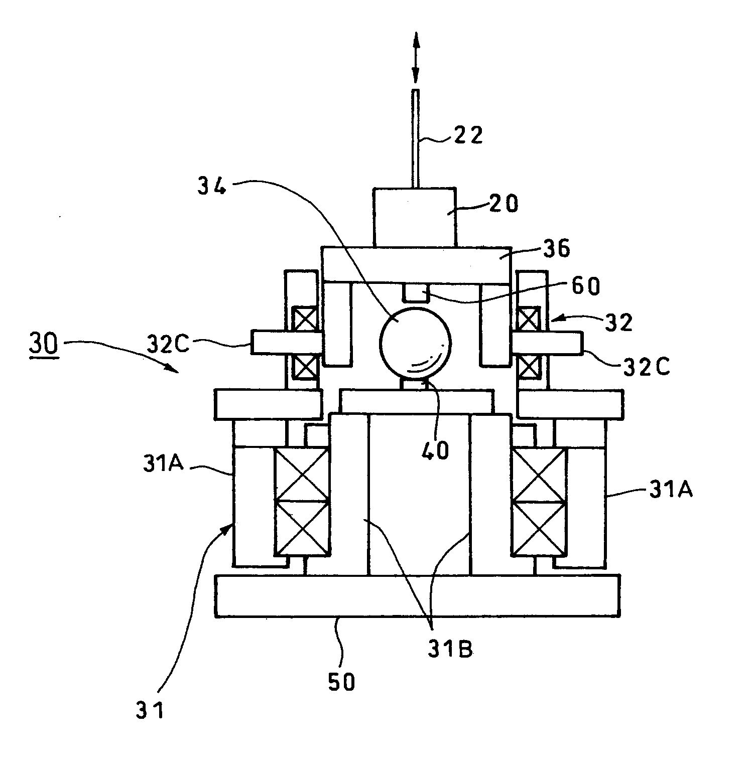
[0035 according to the present invention is, as shown in FIG. 5, such that a fixing portion 31B of the first axis turning mechanism 31 installed at the base portion 50 of an apparatus is disposed at the inner circumference, a reference sphere 34 is disposed thereat via a reference sphere supporting portion 40, and at the same time, a moving portion 31A of the first axis turning mechanism 31 is placed on the outer circumference of the fixing portion 31, and the second axis turning mechanism 32 is mounted thereon.

[0036]In the drawing, reference numeral 60 denotes a displacement gauge that measures changes in the distance between a laser interference measuring apparatus 20 mounted on a carriage 36 and the surface of the reference sphere 34 at the opposite side of the measurement light beam 22.

[0037]For example, a Michelson interferometer may be used as the laser interference measuring apparatus 20.

[0038]The axis 32C of the second axis turning mechanism 32 is divided into two sections w...


PUM


Abstract

An optical axis polarization type laser interferometer including a reference sphere which forms a reference of measurement, a retro-reflecting means disposed at a measurement object, a laser interference measuring apparatus for outputting a measurement value corresponding to an increase or a decrease in the distance to and from the retro-reflecting means; and a two-axis turning mechanism for turning an emission beam of the corresponding laser interference measuring apparatus centering around the reference sphere, which measures, with the center coordinates of the reference sphere used as the reference, the distance to and from the retro-reflecting means where the optical axes of the emission beam from the laser interference measuring apparatus mounted on the two-axis turning mechanism and a return beam become parallel to each other, wherein the fixing portion of the first axis turning mechanism installed at the base part of the apparatus is disposed at the inner circumference thereof, the reference sphere is placed at the fixing portion thereof, and at the same time, the moving portion of the first axis turning mechanism is placed at the outer circumference of the fixing portion, and the second axis turning mechanism is mounted on the moving portion thereof. Therefore, complexities in mechanism design can be simplified to a large extent with respect to the first axis turning mechanism that composes the two-axis turning mechanism.

Description

CROSS-REFERENCE TO RELATED APPLICATION[0001]The disclosure of Japanese Patent Application No. 2007-37410 filed on Feb. 19, 2007 including specifications, drawings and claims is incorporated herein by reference in its entirety.BACKGROUND OF THE INVENTION[0002]1. Field of the Invention[0003]The present invention relates to an optical axis polarization type laser interferometer including a reference sphere which forms a reference of measurement, a retro-reflecting means disposed at a measurement object, a laser interference measuring apparatus for outputting a measurement value corresponding to an increase or a decrease in the distance to and from the retro-reflecting means, and a two-axis turning mechanism for turning an emission beam of the corresponding laser interference measuring apparatus centering around the reference sphere, which measures, with the center coordinates of the reference sphere used as the reference, the distance to and from the retro-reflecting means where the op...

Claims


Application Information

Patent Timeline
IPC IPC(8): G01B9/02
CPCG01S7/4811G01S17/74G01S17/66G01S17/42
Inventor TAKETOMI, NAOYUKIABBE, MAKOTO
Owner MITUTOYO CORP
Why Eureka
Try Eureka