Ceiling fixture mount-facilitating assembly

Active Publication Date: 2008-08-21
IDEAL IND LIGHTING LLC
View PDF8 Cites 2 Cited by
  • Summary
  • Abstract
  • Description
  • Claims
  • Application Information

AI Technical Summary

Benefits of technology

[0003]Although such conventional mounting assemblies provide a satisfactory mounting once the fixture is installed and in the final mounting position, the installation process can be difficult. In view of the foregoing disadvantages seen in known ceiling mounted

Problems solved by technology

Such lighting fixtures present certain challenges in installation and servicing of the fixture.
Fixtures of this type tend to be large and heavy which can make for difficulty in mounting overhead.
Further, during installation or when the fixture needs servicing, the fixture may be left in a vulnerable and unstable position.
However, the Rapp device is relatively complex due to the rigid nature of the bracke

Method used


Image

  • Ceiling fixture mount-facilitating assembly
  • Ceiling fixture mount-facilitating assembly
  • Ceiling fixture mount-facilitating assembly

Examples


Embodiment Construction

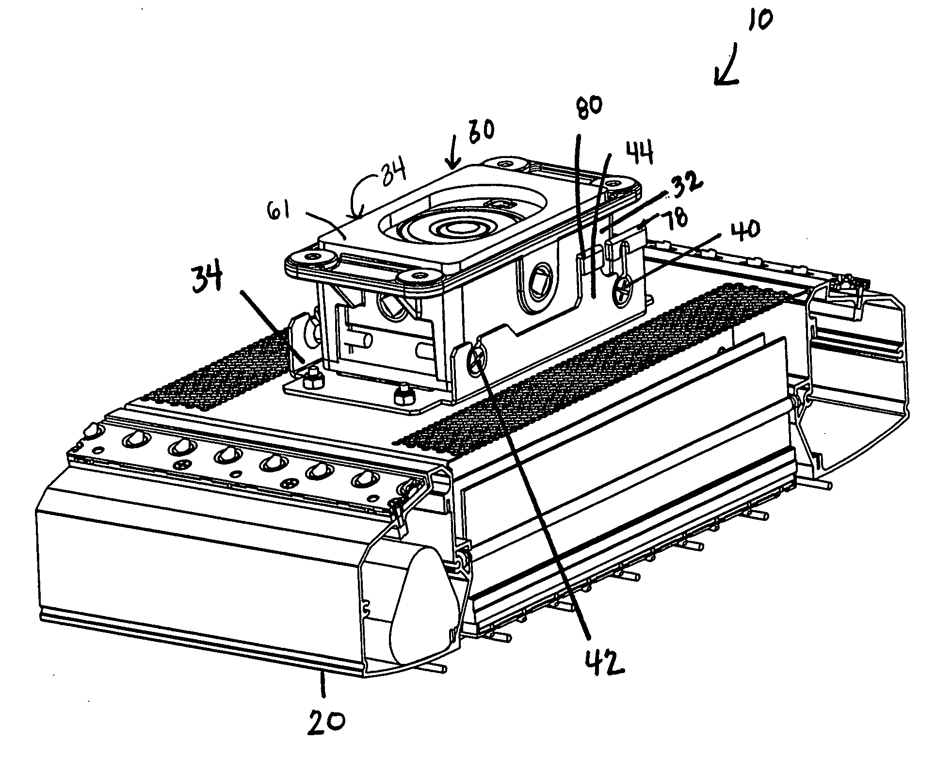
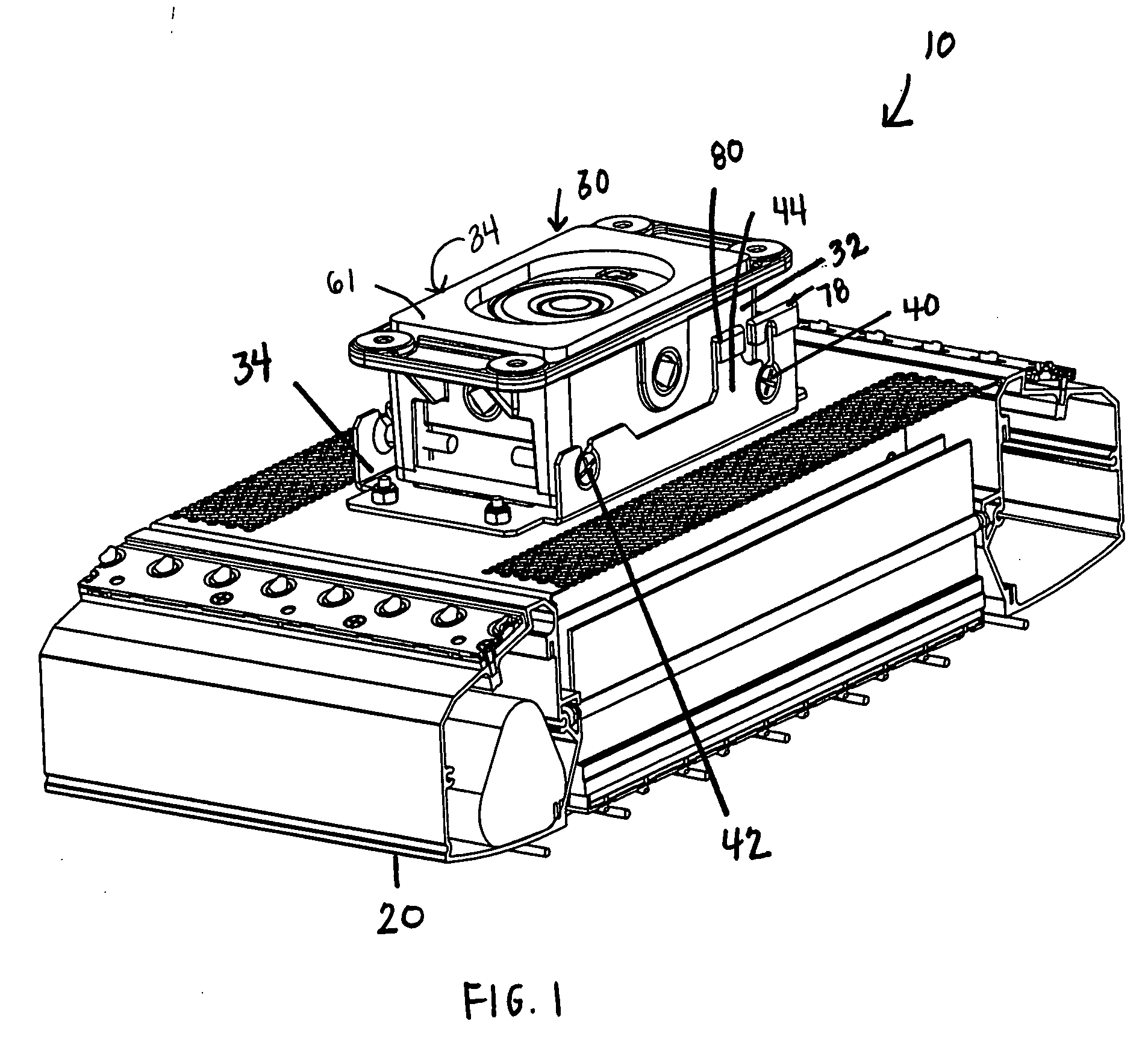
[0028]FIGS. 1-7 illustrate the preferred embodiments of a ceiling fixture mounting assembly in accordance with this invention.

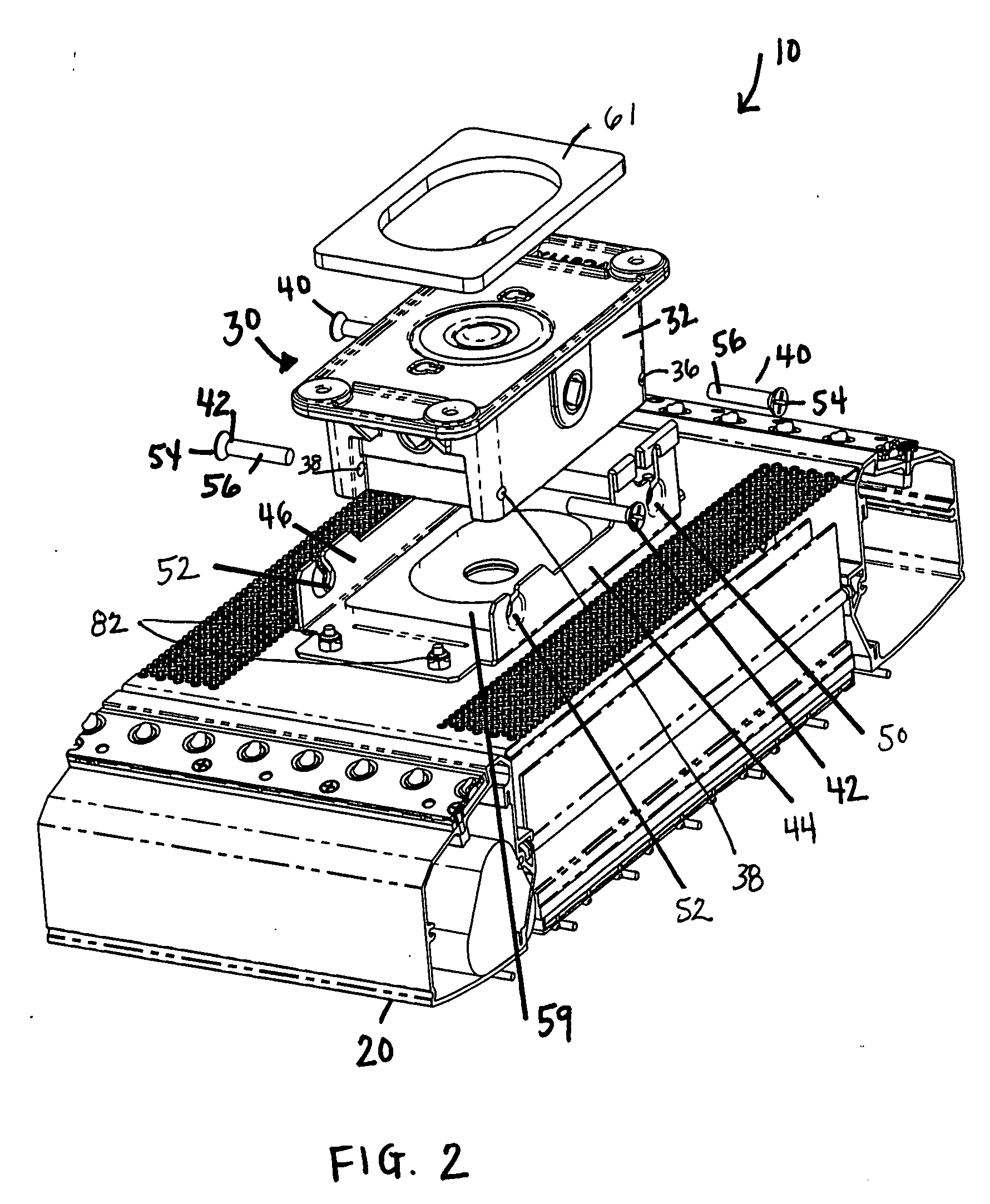
[0029]Referring first to FIG. 1, ceiling fixture mounting assembly 10 includes a box 30 for affixing to a ceiling and contains electrical wiring. Box 30 includes opposite vertical sidewalls, 32 and 34 respectively, each sidewall having first and second laterally spaced threaded holes, 36 and 38 respectively. First and second laterally spaced threaded holes, 36 and 38, receive corresponding first and second fasteners, 40 and 42, respectively, as shown in FIG. 5. Referring to FIGS. 2 and 3, fasteners 40 and 42 preferably have a head 54 and a threaded portion 56 for engagement with first and second laterally spaced threaded holes, 36 and 38.

[0030]Referring still to FIGS. 2 and 3, box 30 further includes two vertical mounting plates, 44 and 46 respectively, each projecting upwardly from the fixture 20 to terminate in an upper edge 48 and positioned to overlie one...


PUM


Abstract

A ceiling fixture mounting assembly including a box for affixing to a ceiling and containing electrical wiring, the box having opposite vertical sidewalls each with first and second laterally spaced threaded holes receiving corresponding first and second fasteners, and two vertical mounting plates each projecting upwardly from the fixture to terminate in an upper edge and positioned to overlie one of the sidewalls and each having first and second ways receiving the first and second fasteners, respectively, the first way configured for supporting the fixture at an angle to the box for connecting the wires, wherein the improvement comprises each fastener having a head and a threaded portion and the first and second ways having first and second mounting slots, respectively, each having a lower closed end and an upper open end and sized smaller than the head, the plate having a recess at the closed end configured to receive the head such that it is in vertical alignment with the open end, thereby holding the plate in position against the box.

Description

FIELD OF THE INVENTION[0001]The present invention related to light-fixture mounting, in particularly to an assembly facilitating fixture mounting to a ceiling.BACKGROUND OF THE INVENTION[0002]Ceiling mounted lighting fixtures are well known in the art and are used in a variety of applications, including for use in commercial, industrial and other institutional settings. Such lighting fixtures present certain challenges in installation and servicing of the fixture. Because the light fixture is ceiling mounted, typically an installer must stand on a ladder to access the fixture. Fixtures of this type tend to be large and heavy which can make for difficulty in mounting overhead. Further, during installation or when the fixture needs servicing, the fixture may be left in a vulnerable and unstable position. For example, U.S. Pat. No. 4,368,506 to Rapp discloses an Apparatus for Mounting a Luminaire to a Ceiling. Rapp states it is an object of the invention to provide an apparatus for mou...

Claims


Application Information

Patent Timeline
IPC IPC(8): F21S8/06
CPCF21V27/02F21V21/03
Inventor KINNUNE, BRIAN L.WILCOX, KURT S.
Owner IDEAL IND LIGHTING LLC
Why Eureka
Try Eureka