Rotating Machine With a Fluid Supply Rotating Column

Inactive Publication Date: 2008-08-21
SIDEL PARTICIPATIONS SAS
View PDF3 Cites 7 Cited by
  • Summary
  • Abstract
  • Description
  • Claims
  • Application Information

AI Technical Summary

Benefits of technology

[0064]There is therefore a pressing demand from users for improvements to be made to the rotating colum

Problems solved by technology

However, there are a number of disadvantages inherent in the structure of this known column.
This operation of removing the electrical commutator 10 is time consuming a

Method used


Image

  • Rotating Machine With a Fluid Supply Rotating Column
  • Rotating Machine With a Fluid Supply Rotating Column
  • Rotating Machine With a Fluid Supply Rotating Column

Examples


second embodiment

[0205]Turning now to FIG. 8, this is a view in longitudinal section through a column element forming a rotating connector according to the invention.

[0206]In this second embodiment, the column element 250 comprises a fixed first assembly 252 provided with six axial conduits 265-270 or parallel fluid passage holes, three of these passage holes 265-267 being shown in solid lines in this FIG. 8 while the other three 268-270 appear in dashes in this figure.

[0207]These parallel axial conduits 265-270 are of different lengths and each communicate:[0208]at the fixed lower part of the element 250, with a radial supply conduit 276-277 (only two radial supply conduits 276-277 are shown in FIG. 8 so as not to overload the figure);[0209]at the moveable upper part of the element 250, with radial holes 281-286 located in a given row and passing through a rotating tubular component or tubular body 280, a fixed shaft 287 and a jacket C.

[0210]Thus, in much the same way as was described with referenc...

first embodiment

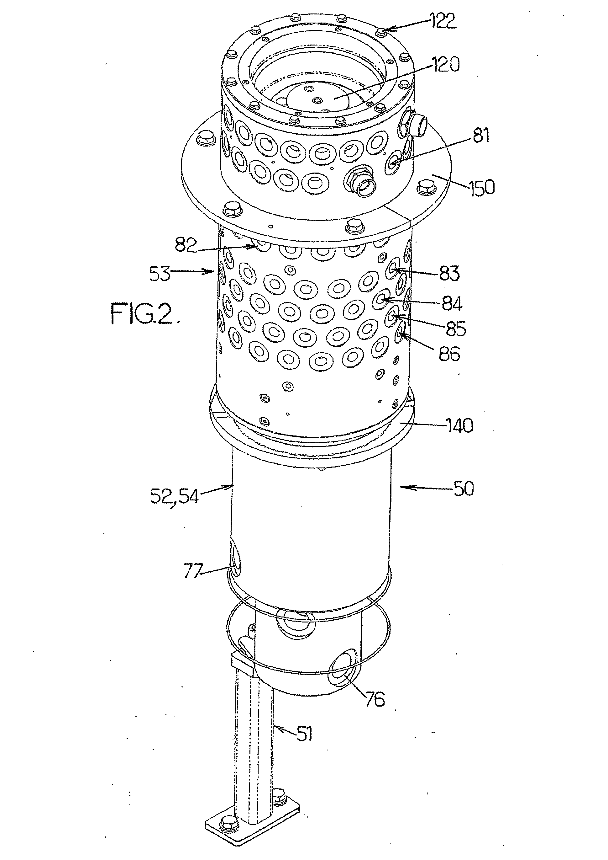
[0227]In the invention as illustrated in FIGS. 2-7, the first assembly 52 comprises a shaft 87 and at least two concentric tubes 65-69, the innermost tube 65 forming a first or axial conduit 65a which has an open end level with the first level of radial through orifices 81 in the tubular body 80, said at least two tubes 65-69 defining between them an axial annular space 70-73, 75 forming a second axial conduit that has an open end level with a second level of radial through orifices 82-86 in the tubular body 80.

[0228]Alternatively, in the second embodiment of the invention, as illustrated in FIG. 8, the first assembly 252 comprises at least two parallel axial conduits 265-269 each having an open end level with a level of radial through orifices 281-286 in the tubular body 280.

[0229]The second assembly 53 is preferably positioned at the top of the column element 50, 250.

[0230]The first assembly 52, 252 comprises a first or lower element 54 extending beneath the tubular body 80, 280 a...


PUM


Abstract

The invention concerns a rotating machine such as a carrousel comprising a rotating frame driven in rotation about an axis of rotation, several working stations supported by the rotating frame, a fluid supplying rotating column, coaxial to the axis column element (50, 250) provided with two assemblies (52, 252, 53) mobile in rotation relative to each other, about said axis of rotation, a first assembly (52, 252) including an axial tubular body (80, 280) provided with at least two tiers of radial through holes (81-86, 281-286), the axial conduits of the first assembly (52, 252) extending over different lengths in the space delimited by said tubular body (80, 280), each conduit (65a, 70-73, 75) emerging perpendicularly to one specific tier of radial through holes (81-86, 281-286), the column element (50, 250) thereby defining a rotating connection dispensing at least two fluids towards the working stations of the machine, and in that a sleeve C is interposed between said tubular body (80, 280) of the second assembly (53) and said first assembly (52, 252).

Description

TECHNICAL FILED[0001]The present invention relates to improvements to carousel-type rotating machines comprising:[0002]a rotating frame revolving about an axis of rotation;[0003]several workstations supported by the rotating frame;[0004]a rotating fluid-supply column coaxial with the axis of rotation of the rotating frame; and[0005]at least one rotating fluid connector located on said column and connected to a fixed source of fluid.[0006]The invention is more particularly concerned with rotating machines for making containers from thermoplastic materials, such as PET, by blow molding or stretch blow molding a preform (or intermediate container) in molds supported by a rotating bed.[0007]The invention can be applied to rotating machines of other types such as filling machines.BACKGROUND OF THE INVENTION[0008]FIG. 1 of the appended drawings shows a side view of a rotating electrical power and fluid supply column currently installed in certain blow molding or stretch blow molding conta...

Claims


Application Information

Patent Timeline
IPC IPC(8): B29C49/36B29C49/42
CPCB29C49/36B29K2067/00B29C49/42
Inventor DANEL, LAURENT
Owner SIDEL PARTICIPATIONS SAS
Why Eureka
Try Eureka