Heat exchanging apparatus

Pending Publication Date: 2022-10-27
HATAMOTO HIROSHI +1
View PDF0 Cites 0 Cited by
  • Summary
  • Abstract
  • Description
  • Claims
  • Application Information

AI Technical Summary

Benefits of technology

The present invention is about a heat exchanger that can be adaptable to different piping conditions, which can save money on manufacturing, management, and installation. Additionally, by eliminating the need for sealing materials, the invention can achieve benefits like reducing parts and simplifying maintenance.

Problems solved by technology

However, the conventional heat exchanging apparatus of the falling liquid film type has a problem that a case to which the heat exchange fluid circulation pipe is attached makes one difficult to clean and maintain the heat exchange fluid circulation pipe.

Method used


Image

  • Heat exchanging apparatus
  • Heat exchanging apparatus
  • Heat exchanging apparatus

Examples


Embodiment Construction

[0030]Hereinafter, embodiments of the present invention will be described with reference to the accompanying drawings.

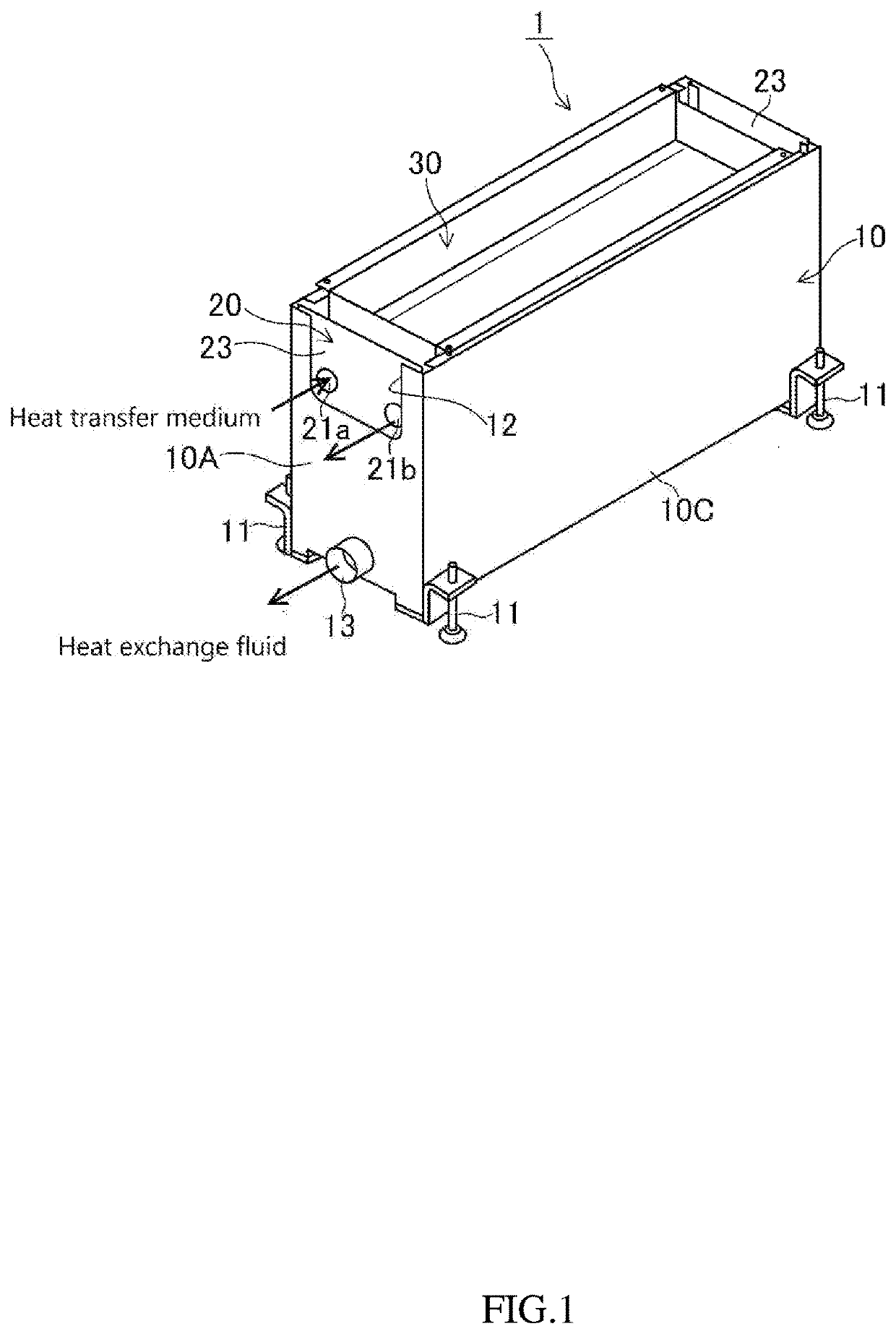
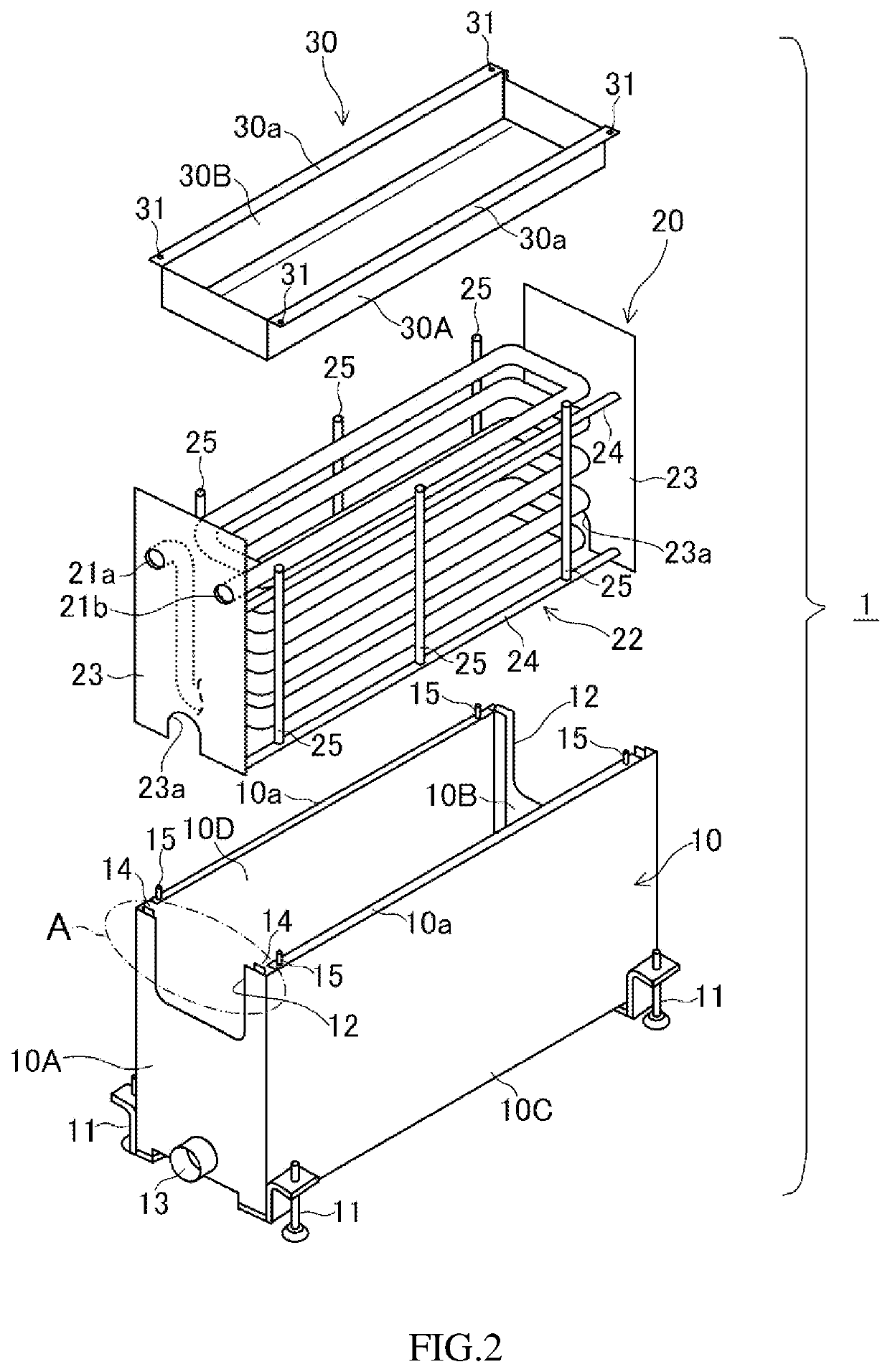
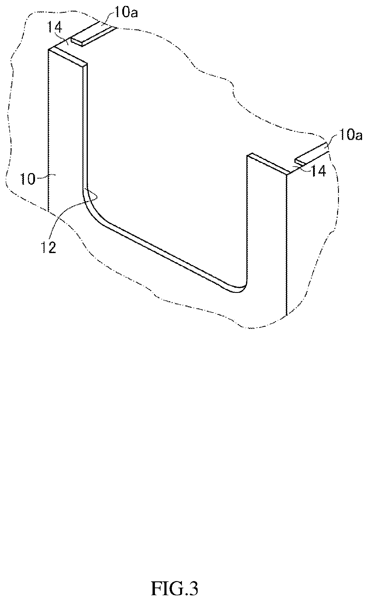
[0031]FIG. 1 is a perspective view of a heat exchanging apparatus according to the present invention, FIG. 2 is an exploded perspective view of the heat exchanging apparatus according to the present invention, FIG. 3 is an enlarged detailed view of part A of FIG. 2, FIG. 4 is a front view of the heat exchange unit of the heat exchanging apparatus according to the present invention, FIG. 5 is a perspective view of the heat exchanging apparatus according to the present invention, of which the heat exchange unit is mounted, horizontally reversed from the state shown in FIG. 1, FIG. 6 is a side view of the heat exchanging apparatus shown in FIG. 5 (namely, a view from the direction of arrow B in FIG. 5), and FIG. 7 is an exploded perspective view of the heat exchanging apparatus shown in FIG. 5. It should be noted that in FIG. 7, the description of the heat transfer medi...


PUM


Abstract

A heat exchanging apparatus is adapted for differences in piping conditions at installation sites, reducing man-hours for manufacturing, management and installation for cost reduction. The heat exchanging apparatus includes a case open upward, a heat exchange unit housed in the case, and a storage tank arranged at an upper section of the case. A heat transfer medium inlet and a heat transfer medium outlet are open in the same direction at both ends of a heat transfer medium circulation pipe. A heat exchange fluid discharge port for discharging heat exchange fluid having dropped in the case is formed on one of side walls of the case either in the same direction as or in the opposite direction to the opening direction of the heat transfer medium inlet and the heat transfer medium outlet so that the heat exchange unit can be vertically taken in and out of the case.

Description

TECHNICAL FIELD[0001]The present invention relates to a heat exchanging apparatus for exchanging heat between a heat exchange fluid and a heat transfer medium flowing through a heat transfer medium circulation pipe of a heat exchange unit.BACKGROUND ART[0002]Conventionally, a heat exchanging apparatus of the falling liquid film type is known for cooling or heating heat exchange fluid by exchanging heat between a heat transfer medium (refrigerant or heat medium) flowing through a heat transfer medium circulation pipe and the heat exchange fluid while the heat exchange fluid flows down by its dead weight along an outer surface of the heat exchange fluid circulation pipe in the form of a liquid film. For instance, refer to Patent Document 1.[0003]However, the conventional heat exchanging apparatus of the falling liquid film type has a problem that a case to which the heat exchange fluid circulation pipe is attached makes one difficult to clean and maintain the heat exchange fluid circu...

Claims


Application Information

Patent Timeline
IPC IPC(8): F28D7/02F28D3/02F28F9/00F28F9/02
CPCF28D7/022F28D3/02F28F9/001F28F9/0246F28F2230/00F28D5/02F28F9/00F28D7/02F28D7/082Y02E60/14
Inventor HATAMOTO, HIROSHIMITSUYASU, TADASHI
Owner HATAMOTO HIROSHI
Why Eureka
Try Eureka