
A tire safety monitoring device

A technology for safety monitoring and tires, applied in tire measurement, road vehicle tires, tire parts, etc., can solve problems such as difficult to measure tire wear, reduce service life, and safety hazards, and achieve the goal of simplifying tire maintenance and improving safety Effect

Active Publication Date: 2017-05-10
刘伟
View PDF9 Cites 0 Cited by
  • Summary
  • Abstract
  • Description
  • Claims
  • Application Information

AI Technical Summary

Problems solved by technology

If it is not dealt with in time, it is very likely that when the car is driving at high speed, the sundries will be pressed by the ground and squeeze the rubber on both sides, causing cracks in the tires, reducing the service life, and even blowing out the tires in severe cases.
[0004] For different sundries, it needs to be judged. If it is a stone, just take it out. If it is a metal object such as a nail, it is impossible to judge whether it has pierced the surface of the tire. The tire is flat and the car loses the ability to drive, so the nail cannot be pulled out immediately, but the car should be driven at a low speed to the nearest repair shop for processing
For such a situation, it still relies on the driver to stop and visually inspect it, or the maintenance personnel to visually inspect it during maintenance, and there is still a great potential safety hazard
[0005] The prior art CN20080120013 mentions a device for evaluating the appearance of the tire surface, which utilizes the reflection of the tire surface and uses a linear color camera to obtain the cleaning image of the tire surface, but the structure of the linear camera used in this invention is complex and requires special detection The camera placed on the stand is difficult to directly apply to the car, and can only take two-dimensional images of the tire surface, which is inconvenient for post-processing, and cannot automatically judge the stones, nails and other sundries on the tire surface
[0006] In the prior art CN201080031750, a tire inspection device is mentioned in the appearance inspection of the inner and outer surfaces of the tire by efficiently photographing the tire to shorten the inspection time and synthesizing the captured images with high precision. The camera images of the inner peripheral surface of the tire obtained by multiple cameras that are relatively shifted upward and have different imaging positions in the width direction of the tire are synthesized to inspect defects on the inner and outer surfaces of the tire. Due to the complex structure of the device, Multiple cameras are required to shoot at the same time, and the location of each camera is strictly required, so it is difficult to install on the car, so it can only be used for the detection of tires after production, and it is difficult to apply to the daily safety monitoring of cars
[0007] A tire wear measuring device mentioned in the prior art CN200910265999 uses a cosine grating arranged inside the lens to irradiate light onto the tire surface before and after driving, and then uses a digital camera to measure the intensity of light irradiated on the tire surface. To analyze the wear state of tires, the device has a simple structure and can effectively measure tire wear, but it depends on the reflection of light on the tire surface. When the tire surface is stained with debris, such as rain, it will be difficult to measure due to poor reflection effect Tire wear, can not automatically judge the stones, nails and other sundries on the tire surface

Method used


Image

  • A tire safety monitoring device
  • A tire safety monitoring device
  • A tire safety monitoring device

Examples


Embodiment Construction

[0031] "Front", "rear", "inside" and "outside" described in the present invention are the relative positions when the tire is installed on the automobile, and have nothing to do with the specific structure of the present invention.

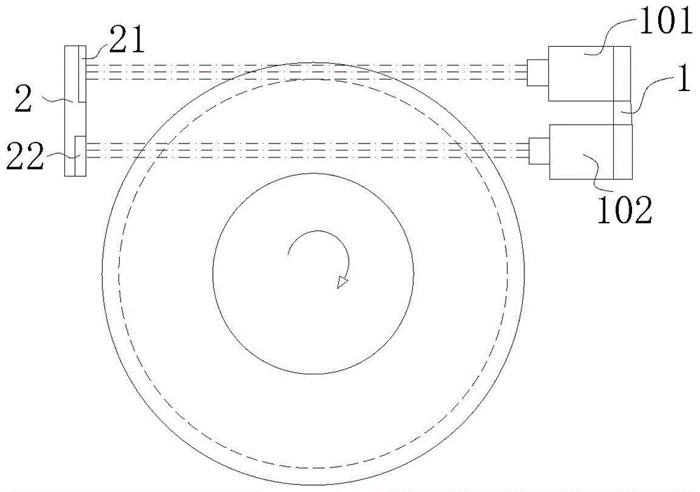
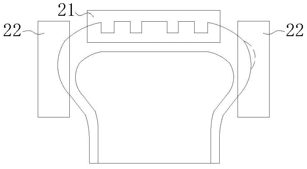
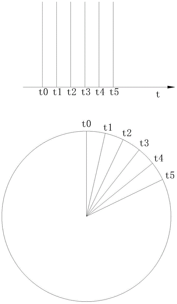
[0032] Such as Figure 1-5As shown, a tire safety monitoring device includes a limit block 61 installed on the tire for checking the depth of the longitudinal groove of the tire tread. The limit block 61 is provided with a metal calibration sheet. The tire front, A light source assembly 1 placed horizontally is installed on the inner lining of the fender of the automobile, and the light source assembly 1 includes a first lamp group 101, the height of the first lamp group 101 is consistent with the height of the upper surface of the tire, and the first lamp group The light emitted by 101 is perpendicular to the cross-section of the tire longitudinal groove passing through the center line of the tire and along the vertical direction. After passing t...


PUM


Abstract

The invention particularly relates to a tire safety monitoring device which comprises a light source assembly horizontally arranged in the vehicle running direction. Light emitted by the light source assembly is perpendicular to the tire center line and a tire section in the vertical direction, and the light is irradiated to a development assembly after passing a longitudinal groove of a tire. The development assembly comprises a first light-sensitive pressing plate, after the first light-sensitive pressing plate is irradiated by the light, the section shape of the longitudinal groove of the tire is output to a processor, and the processor draws the section shape of the longitudinal groove of the tire into a three-dimensional model of the tire. The process is connected with a display device. A metal detector is arranged nearby a tire shoulder on one side of the tire, and a metal receiver is arranged nearby a tire shoulder on the other side of the tire. When a large stone or nail or other sundries are stuck into pattern grooves, a driver can be reminded to handle the sundries in time, and safety of the tire in the vehicle running process is greatly improved.

Description

technical field [0001] The invention relates to the field of automobile active safety monitoring, in particular to a tire safety monitoring device. Background technique [0002] At present, most of the tires used by cars on the market are ordinary pattern tires. The pattern is composed of longitudinal grooves for drainage and transverse grooves for increasing lateral force. The existing tire safety monitoring devices only monitor the pressure of the tires. , When the tire pressure is abnormal, the alarm prompts the driver. The tread pattern of the tire will be worn during use. When the depth of the tread wears to the limit, if the tire continues to be used, it is very likely to cause a blowout. After the car has been driving for a long time, the inspection of the tread depth currently only relies on the driver to observe the limit block set on the tire when parking, and there is no relevant monitoring device to monitor the tire tread depth. If the driver is inexperienced or ...

Claims


Application Information

Patent Timeline
Patent Type & Authority Patents(China)
IPC IPC(8): B60C23/00
CPCB60C19/00B60C23/00B60C2200/04
Inventor 陈子龙
Owner 刘伟
Learn More