Manual pilot combined operating valve for hydraulic support

A technology of hydraulic supports and pilot valves, which is applied in the direction of pillars/supports, servo motor components, fluid pressure actuators, etc., can solve problems affecting labor efficiency, fatigue, and labor-intensive operations of staff, so as to reduce manual operating force and improve The effect of speed of operation and simplification of maintenance links

Inactive Publication Date: 2013-10-23
SHANDONG UNIV OF SCI & TECH
View PDF0 Cites 0 Cited by
  • Summary
  • Abstract
  • Description
  • Claims
  • Application Information

AI Technical Summary

Problems solved by technology

Since the direction of the high-pressure emulsion is controlled by moving the handle back and forth by hand during operation, the operation is laborious for the staff, and long-term work is likely to cause fatigue, which affects the improvement of labor efficiency.

Method used


Image

  • Manual pilot combined operating valve for hydraulic support
  • Manual pilot combined operating valve for hydraulic support

Examples


Embodiment Construction

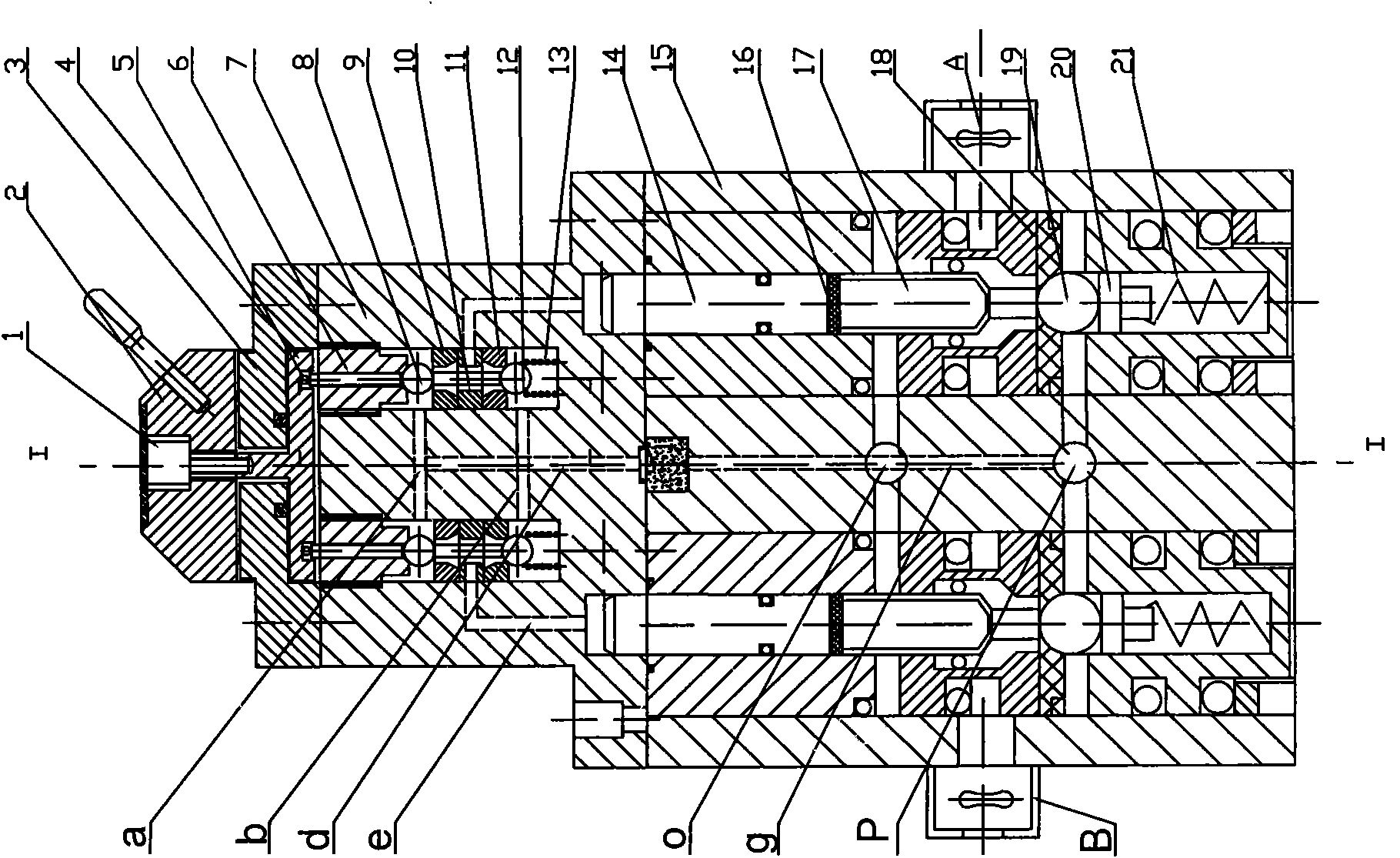
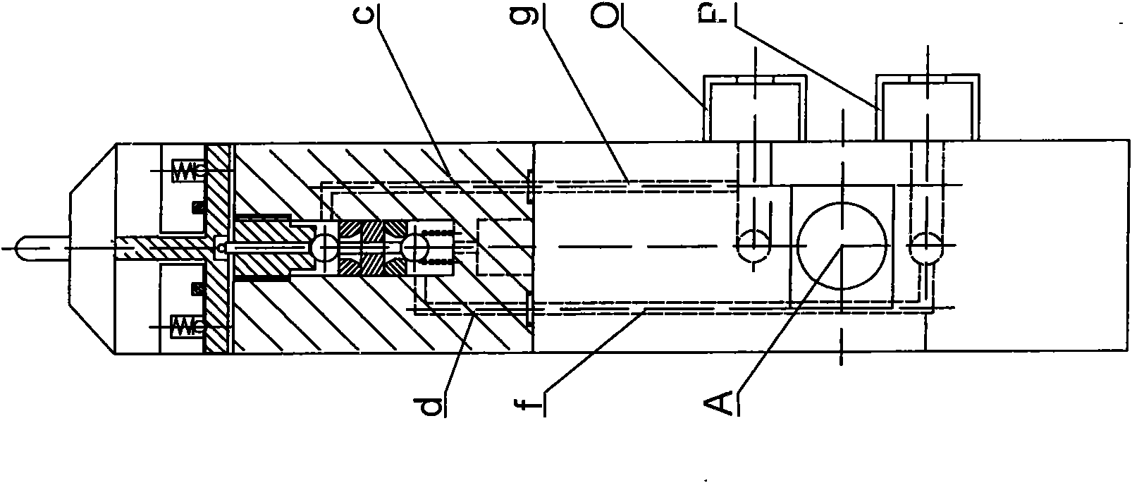
[0021] Such as figure 1 with figure 2 As shown, the present invention mainly comprises a handle control mechanism, a main control valve of a large flow rate and a pilot valve of a small flow rate.

[0022] The main control valve includes a housing 15, main oil ports A and B on the housing, and two valve chambers in the housing 15; the valve chamber is provided with a main valve spring 21 and a spring seat 20 sequentially from bottom to top. , Main valve ball core 19, main valve ball seat 18, main valve core 17, valve pad 16 and main valve core control rod 14. Two vertical oil passages are also processed in the housing 15 of the main control valve, one of which is a low-pressure oil passage g, and the low-pressure oil passage g connects the low-pressure oil port 0 of the main control valve with the low-pressure oil passage of the pilot valve. c is connected, and the other vertical oil passage is high-pressure oil passage f, which connects the high-pressure oil port P of the ...


PUM


Abstract

The invention discloses a manual pilot combined operating valve for a hydraulic support. The operating valve mainly comprises a handle control mechanism, a high-flow main control valve and a low-flow pilot valve, wherein, the high-flow main control valve can be controlled only by lightly turning the low-flow pilot valve, thus achieving reliable action and convenient operation, lowering manual operating force and being beneficial to improving the stability and reliability of overall system operation.

Description

technical field [0001] The invention relates to a coal mine hydraulic support control valve. Background technique [0002] At present, the operation of hydraulic support in coal mines is mainly carried out with manual sheet valves. The structure of the manual slice valve is a symmetrical partial mechanism, which is composed of upper and lower parts. The upper part is a direct handle control mechanism, and the lower part is a large flow main control valve. The handle control mechanism is composed of a handle installed on the upper cover, two sets of pressing blocks in the upper cover and a compression spring; the main control valve includes a housing, two main oil ports on the housing and two valve chambers in the housing , the main valve spring, spring seat, main valve ball core, main valve ball seat, main valve core, valve pad and main valve core control rod are sequentially arranged in the valve chamber from bottom to top. The lower pressing block of the handle control m...

Claims


Application Information

Patent Timeline
Patent Type & Authority Patents(China)
IPC IPC(8): F15B13/042E21D15/51
Inventor 徐瑞银程百林郭凡灿袁建军
Owner SHANDONG UNIV OF SCI & TECH
Why Eureka
Try Eureka