System and method for distinguishing leaks from a disengaged canister condition in a reduced pressure treatment system

a treatment system and disengaged canister technology, applied in the field of tissue treatment systems, can solve the problems of presenting errors in the final flow rate determination, affecting the flow rate of the system, so as to reduce the pressure at the tissue site, reduce the pressure, and reduce the pressure

Active Publication Date: 2008-08-21
KCI LICENSING INC
View PDF101 Cites 89 Cited by
  • Summary
  • Abstract
  • Description
  • Claims
  • Application Information

AI Technical Summary

Benefits of technology

[0007]The problems presented by existing detection systems are solved by the systems and methods of the illustrative embodiments described herein. In one embodiment, a reduced pressure treatment system is provided and includes a processing unit, a reduced pressure source, and a conduit fluidly connected between the reduced pressure source and a tissue site of a patient. The reduced pressure source is configured to operate at a target power level to apply a reduced pressure to the tissue site. The reduced pressure treatment system further includes a canister in fluid communication with the conduit and the reduced pressure source for collecting fluid drawn from the tissue site. A drape is configured for position

Problems solved by technology

One problem with current reduced pressure systems is the interruption of reduced pressure to the tissue site when a leak develops in the system or a component of the system, such as a fluid collection canister, becomes disengaged.
The flow sensors also may exhibit decreased accuracy due t

Method used


Image

  • System and method for distinguishing leaks from a disengaged canister condition in a reduced pressure treatment system
  • System and method for distinguishing leaks from a disengaged canister condition in a reduced pressure treatment system
  • System and method for distinguishing leaks from a disengaged canister condition in a reduced pressure treatment system

Examples


Embodiment Construction

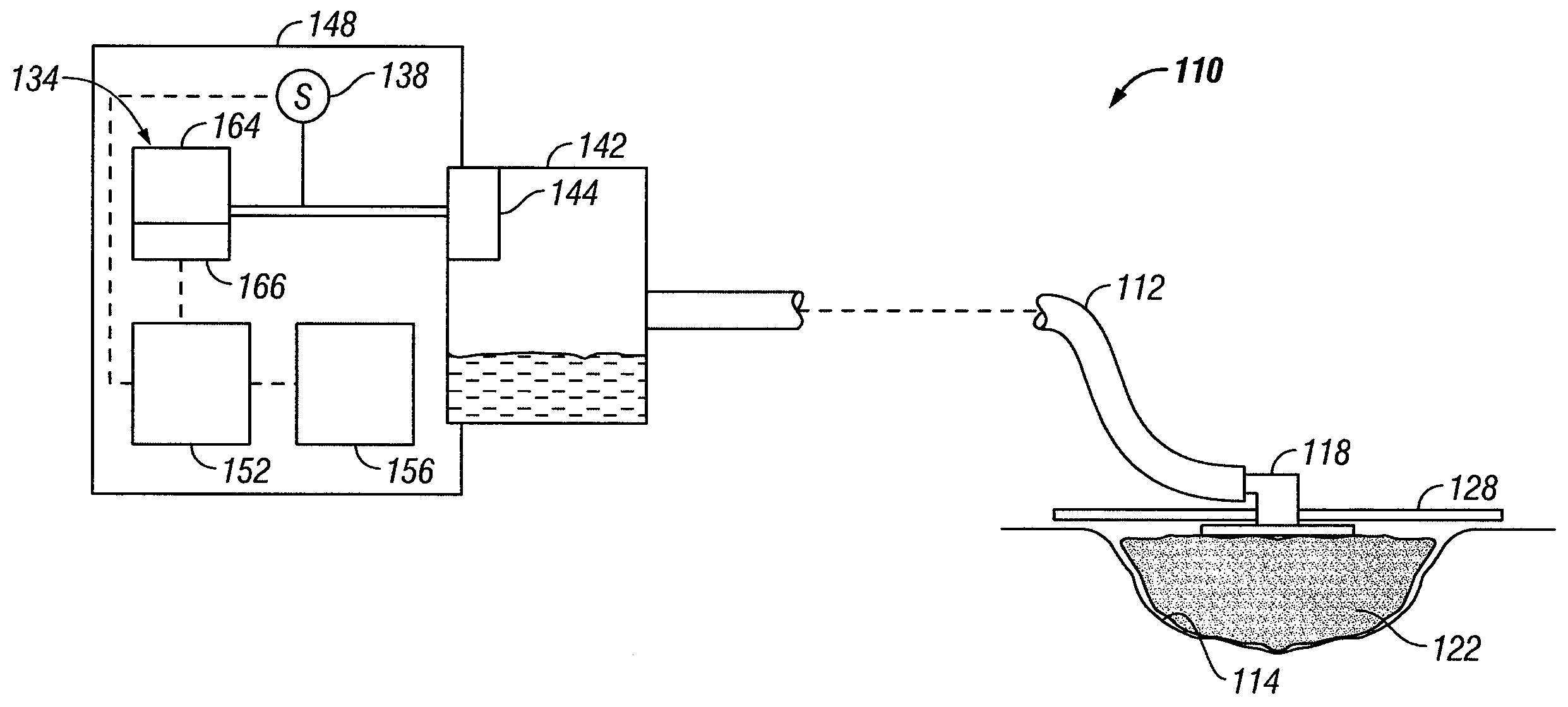
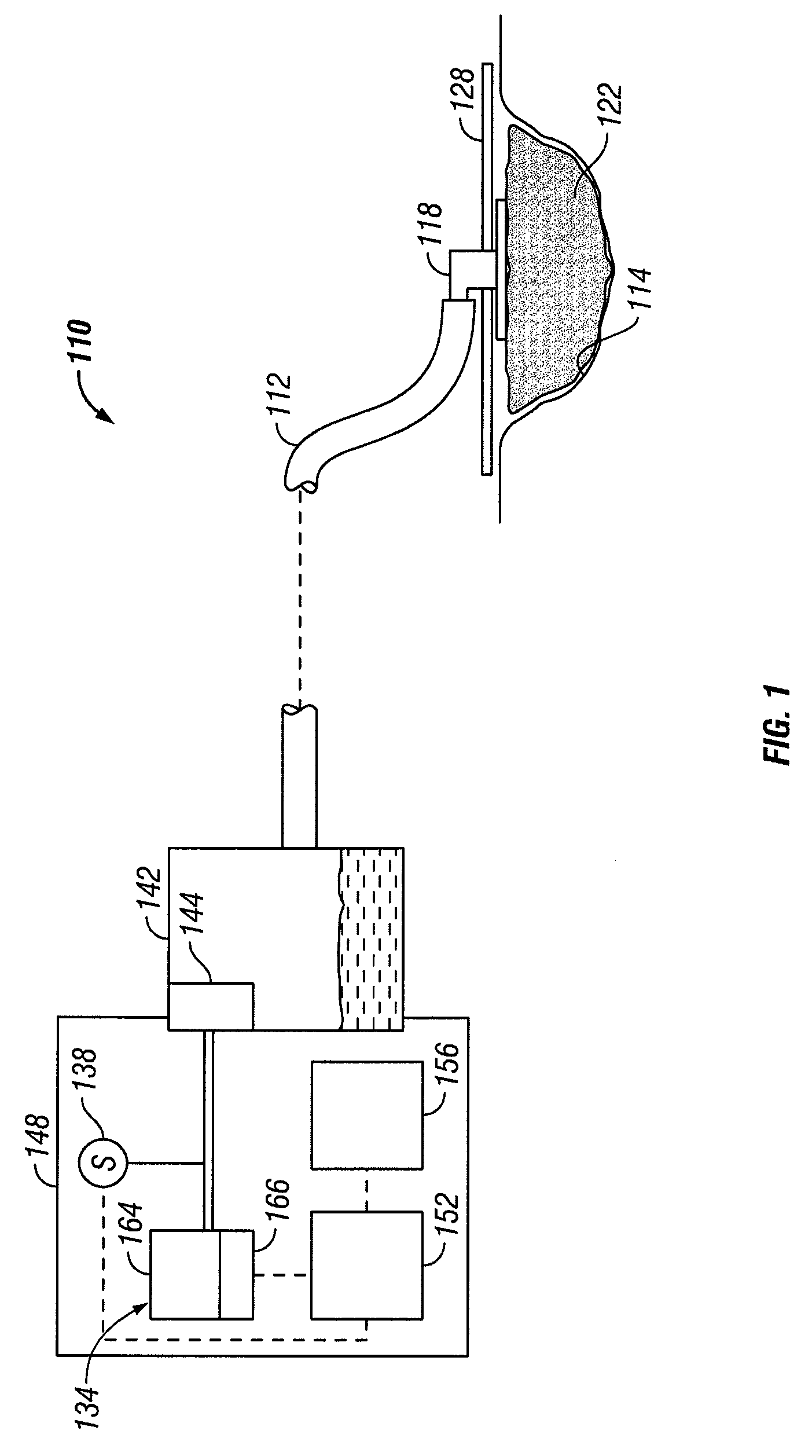
[0013]In the following detailed description of the illustrative embodiments, reference is made to the accompanying drawings that form a part hereof. These embodiments are described in sufficient detail to enable those skilled in the art to practice the invention, and it is understood that other embodiments may be utilized and that logical structural, mechanical, electrical, and chemical changes may be made without departing from the spirit or scope of the invention. To avoid detail not necessary to enable those skilled in the art to practice the embodiments described herein, the description may omit certain information known to those skilled in the art. The following detailed description is, therefore, not to be taken in a limiting sense, and the scope of the invention is defined only by the appended claims.

[0014]The term “reduced pressure” as used herein generally refers to a pressure less than the ambient pressure at a tissue site that is being subjected to treatment. In most case...


PUM


Abstract

A reduced pressure treatment system includes a processing unit, a reduced pressure source, and a conduit fluidly connected between the reduced pressure source and a tissue site of a patient. The reduced pressure source is configured to operate at a target power level to apply a reduced pressure to the tissue site. A canister is provided to collect fluid drawn from the tissue site. A sensor is provided in communication with the reduced pressure source to determine a source pressure at the reduced pressure source, and an alarm indicator is provided in communication with the processing unit. The processing unit communicates a leak alarm signal or a canister disengaged alarm signal to the alarm indicator when an actual power level of the reduced pressure source exceeds the target power level for a selected period of time.

Description

CROSS-REFERENCE TO RELATED APPLICATIONS[0001]This application claims the benefit of U.S. Provisional Application No. 60 / 902,267, filed Feb. 20, 2007, which is hereby incorporated by reference.BACKGROUND[0002]1. Field of the Invention[0003]The present invention relates generally to tissue treatment systems and in particular to a reduced pressure treatment system having a system for distinguishing between a leak condition and a disengaged canister condition.[0004]2. Description of Related Art[0005]Clinical studies and practice have shown that providing a reduced pressure in proximity to a tissue site augments and accelerates the growth of new tissue at the tissue site. The applications of this phenomenon are numerous, but application of reduced pressure has been particularly successful in treating wounds. This treatment (frequently referred to in the medical community as “negative pressure wound therapy,”“reduced pressure therapy,” or “vacuum therapy”) provides a number of benefits, i...

Claims


Application Information

Patent Timeline
IPC IPC(8): A61F5/00
CPCA61M1/0031A61M1/0088A61M2205/14G08B31/00A61M2205/18G08B19/00A61M2205/15A61M1/74A61M1/98A61M1/00A61M27/00A61F13/00
Inventor LAWHORN, THOMAS P.
Owner KCI LICENSING INC
Why Eureka
Try Eureka