Calculation apparatus, program, calculation system and calculation method for production plan

a production plan and calculation system technology, applied in the direction of instruments, electric programme control, data processing applications, etc., can solve the problem of not being able to make a flexible production plan adaptable to the circumstances of the production request-issuing sid

Inactive Publication Date: 2008-08-21
HITACHI LTD
View PDF5 Cites 7 Cited by
  • Summary
  • Abstract
  • Description
  • Claims
  • Application Information

AI Technical Summary

Benefits of technology

[0008]To solve the above problem, the present invention provides a technique that can calculate producible quantities by employing a plurality of meth

Problems solved by technology

The producible quantity, however, is calculated on the basis of a specific method of postponement processing or a specific priority or

Method used


Image

  • Calculation apparatus, program, calculation system and calculation method for production plan
  • Calculation apparatus, program, calculation system and calculation method for production plan
  • Calculation apparatus, program, calculation system and calculation method for production plan

Examples


first embodiment

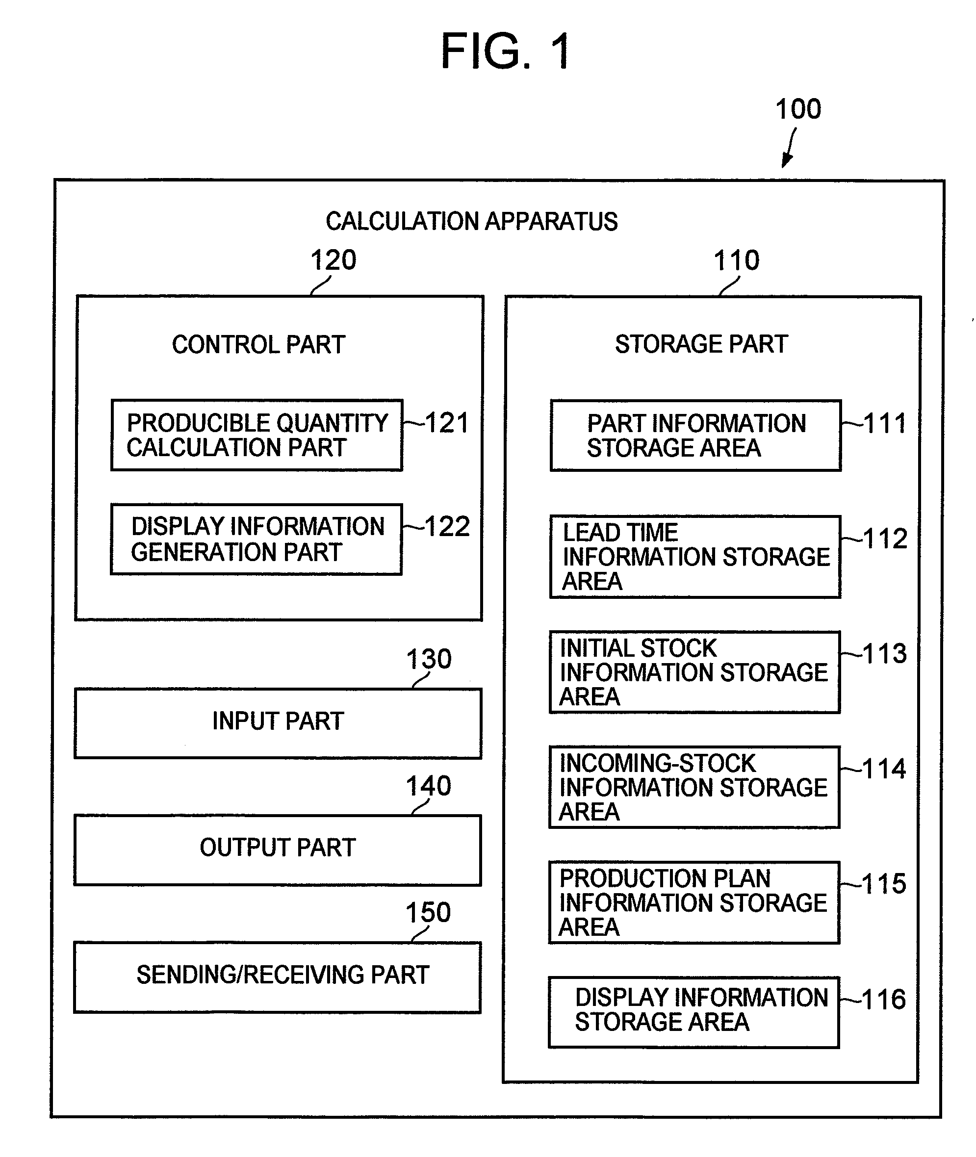
[0035]FIG. 1 is a schematic diagram showing a calculation apparatus 100 as the present invention.

[0036]The calculation apparatus 100 comprises a storage part 110, a control part 120, an input part 130, an output part 140 and a sending / receiving part 150.

[0037]The storage part 110 comprises a part information storage area 111, a lead time information storage area 112, an initial stock information storage area 113, an incoming-stock information storage area 114, a production plan information storage area 115 and a display information storage area 116.

[0038]The part information storage area 111 stores information that specifies a part (i.e. an intermediate product or member) as a component of a product or another part and its quantity required to construct one unit of that product or part.

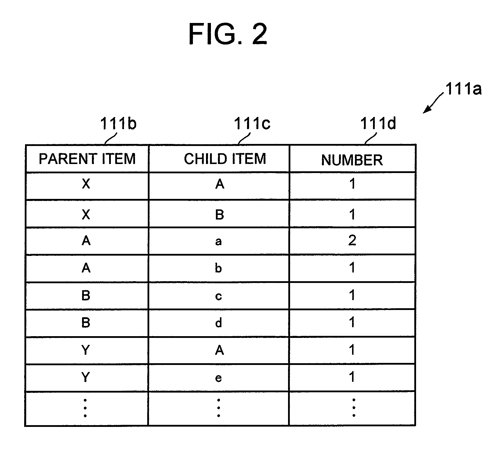
[0039]For example, the part information storage area 111 stores a part table 111a as shown in FIG. 2 (a schematic diagram showing the part table 111a).

[0040]The part table 111a has a parent item field...

second embodiment

[0138]FIG. 15 is a schematic diagram showing a calculation apparatus 200 as the present invention.

[0139]As shown in the figure, the calculation apparatus 200 comprises a storage part 210, a control part, an input part 230, an output part140 and a sending / receiving part 150. Since the storage part 210, the control part 220 and the input part 230 are different from the ones in the first embodiment, these differences will be described below.

[0140]The storage part 210 in the present embodiment comprises a part information storage area 111, a lead time information storage area 112, an initial stock information storage area 113, an incoming-stock information storage area 114, a production plan information storage area 215 and a display information storage area 216. The part information storage area 111, the lead time information storage area 112, the initial stock information storage area 113 and the incoming-stock information storage area are the same as in the first embodiment, and thei...

third embodiment

[0169]FIG. 18 is a schematic diagram showing a calculation apparatus 300 as the present invention.

[0170]As shown in the figure, the calculation apparatus 300 comprises a storage part 310, a control part 320, an input part 330, an output part 140 and a sending / receiving part 150. In comparison with the first embodiment, since the storage part 310, the control part 320 and the input part 330 are different, these differences will be described below.

[0171]The storage part 310 of the present embodiment comprises a part information storage area 111, a lead time information storage area 112, an initial stock information storage area 113, an incoming-stock information storage area 114, a production plan information storage area 315 and a display information storage area 316. The part information storage area 111, the lead time information storage area 112, the initial stock information storage area 113 and the incoming-stock information storage area 114 are similar to the first embodiment, ...


PUM


Abstract

A technique that can make a flexible production plan adaptable to circumstances of a production request-issuing side.
A producible quantity calculation part performs Material Requirements Planning for obtaining a producible quantity and a possible production date, with respect to production request information that has at least one production request specifying a requested production quantity of a product, a requested production date, and a priority. If the producible quantity calculation part judges that a requested production quantity in one production request cannot be produced by the requested production date in that production request, then the producible quantity calculation part postpones the requested production date to a later date according to a plurality of methods, to obtain producible quantities and possible production dates. The producible quantity calculation part generates image data that display, in a table, the producible quantities and possible production dates obtained by the methods.

Description

[0001]The present application claims a priority from Japanese application no. 2007-038250 filed on Feb. 19, 2007, the content of which is hereby incorporated by reference into this application.BACKGROUND OF THE INVENTION[0002]The present invention relates to a technique associated with Material Requirements Planning for obtaining the producible quantity and the possible production date with respect to production request information.[0003]A technique is known that employs Material Requirements Planning (hereinafter, referred to as MRP) for calculating a producible quantity with respect to a requested production quantity, in order to make a production plan.[0004]For example, the technique described in Patent Document 1 calculates a producible quantity, and makes a production plan in which a shortage of a part does not occur since the requested production date is postponed to a later date (postponement processing) if there is a lack of a part in producing the requested quantity.[0005]P...

Claims


Application Information

Patent Timeline
IPC IPC(8): G06Q10/00G05B19/418G06Q50/00G06Q50/04
CPCG06Q10/06312G06Q10/06
Inventor UENO, HIDENORIKANEKO, HIROYUKI
Owner HITACHI LTD
Why Eureka
Try Eureka