Electric nibbler

a technology of electric nibbler and electric ring, which is applied in the field of electric hand tools, can solve the problems of inability to control the conventional electric nibbler, material waste and working space, and the momentum of the punch pin, etc., and achieve the effect of safe use, convenient and quick

Inactive Publication Date: 2008-08-28
TECHWAY INDAL
View PDF20 Cites 9 Cited by
  • Summary
  • Abstract
  • Description
  • Claims
  • Application Information

AI Technical Summary

Benefits of technology

[0012]The main objective of the present invention is to provide ...

Problems solved by technology

1. When a sheetmetal is cut with the conventional electric nibbler (60), the metal filings are produced by the punch pin (63), and this will cause material waste and the working space dirty.
2. Furthermore, the momentum of the punch pin (63) is large, and the user cannot control the conventional electric nibbler (60) easily and may get hurt by the punch pin (63).
3. When the sheetmetal is...

Method used


Image

  • Electric nibbler
  • Electric nibbler
  • Electric nibbler

Examples


Embodiment Construction

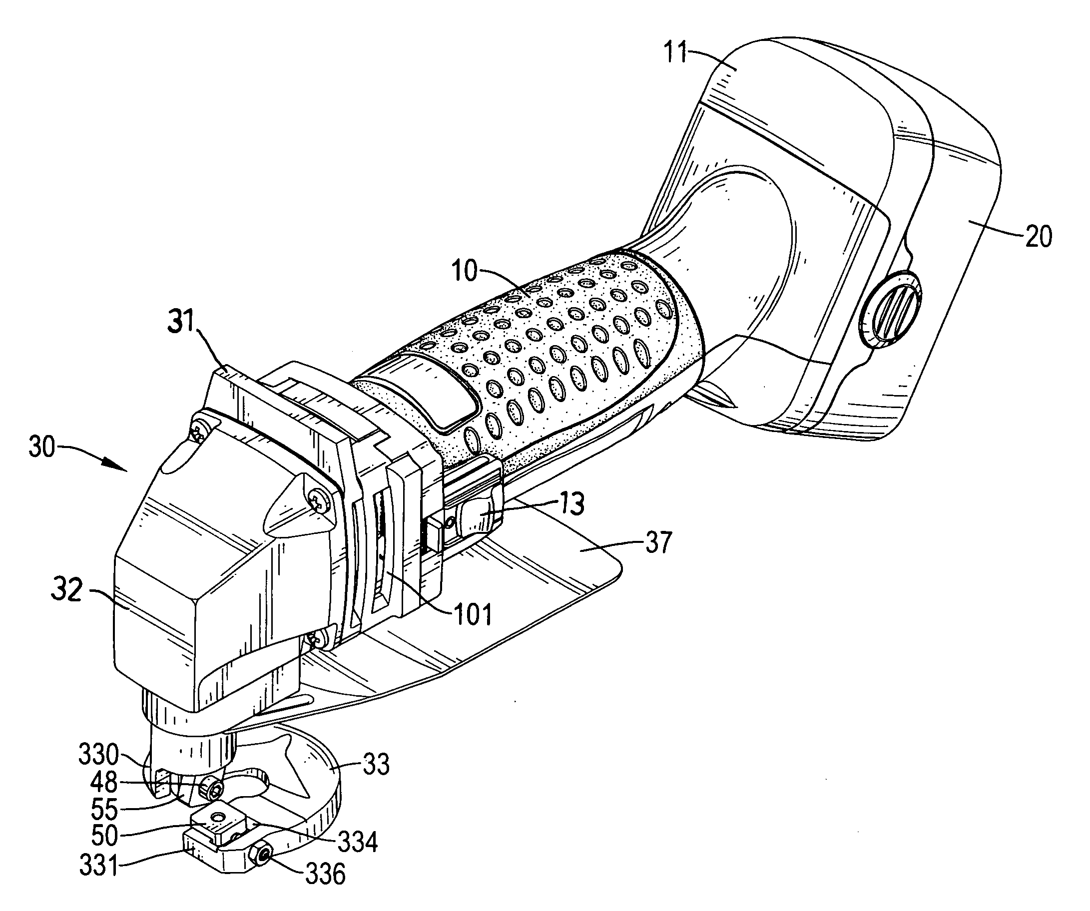
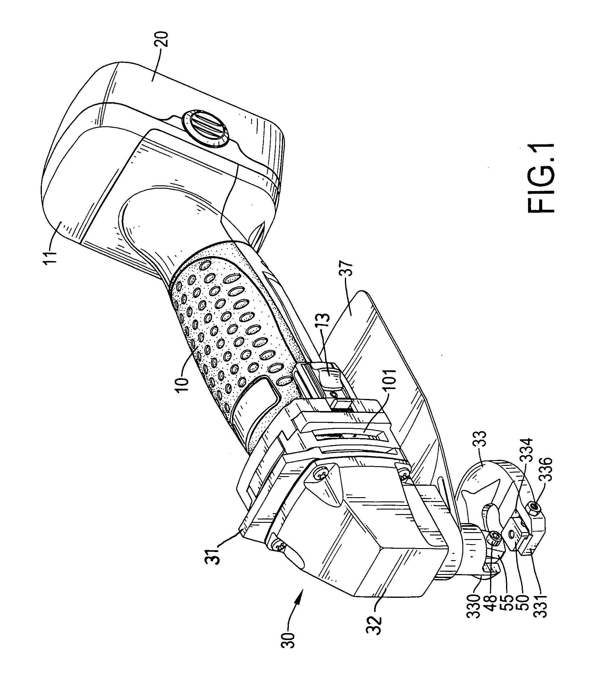
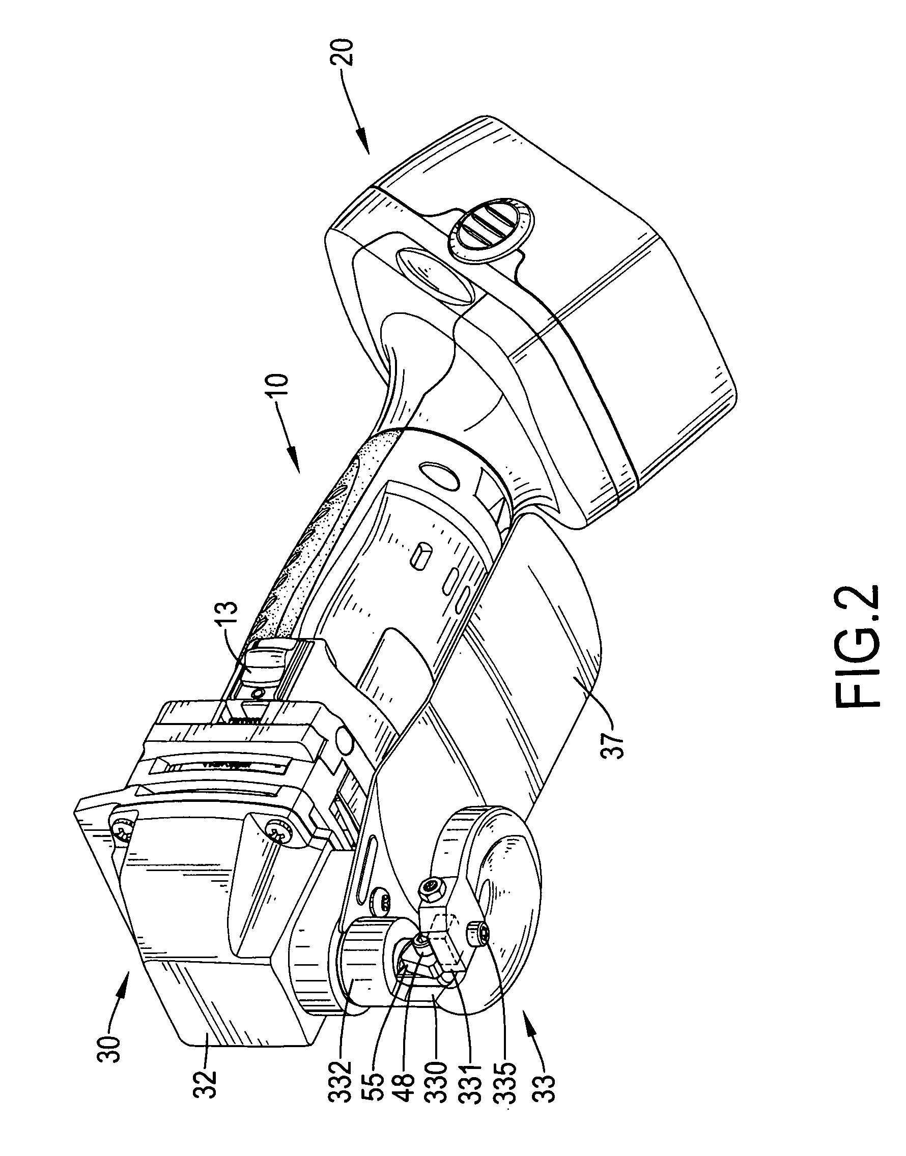
[0024]With reference to FIGS. 1 to 3, an electric nibbler in accordance with the present invention comprises a handle (10), a battery package (20), a front cover (30), a base (33), a lower blade (50), an optional safety plate (37), a drive device (15), a transmitting device (40) and an upper blade (55).

[0025]The handle (10) is hollow, is implemented with two half-casings and has a front end, a rear end, an interior, an outer surface, a battery seat (11), multiple ventilating holes (101) and a switch (13). The battery seat (11) is formed on the rear end of the handle (10). The ventilating holes (101) are formed through the outer surface of the handle (10) between the front end and the rear end and are communicated with the interior of the handle (10). The switch (13) is mounted on the outer surface of the handle (10) near the front end.

[0026]The battery package (20) is detachably attached to the battery seat (11) of the handle (10), is electrically connected to the switch (13) of the...


PUM

PropertyMeasurementUnit
Angleaaaaaaaaaa

Abstract

An electric nibbler has a handle, a battery package, a front cover, a base, a lower blade, a drive device, a transmitting device and an upper blade. The battery package is detachably attached to the battery seat of the handle. The front cover is mounted securely to the handle and has a mounting bracket and a housing. The base is connected securely to the housing and has an upper segment and a lower segment. The lower blade is connected securely to the lower segment. The drive device is mounted in the handle and a drive shaft. The transmitting device is connected to the drive device and has a connecting tube, a transmitting shaft, a drive axle, a gear wheel, a crank and a piston rod. The upper blade is connected securely to the bottom end of the piston rod.

Description

BACKGROUND OF THE INVENTION[0001]1. Field of the Invention[0002]The present invention relates to an electric hand tool, and more particularly relates to an electric nibbler that can be used safely, conveniently and quickly.[0003]2. Description of Related Art[0004]With reference to FIG. 7, a conventional electric nibbler (60) is used to cut a sheetmetal and has a handle and an operating head. The handle has a front end, a rear end and a power cord. The power cord is connected to the rear end of the handle, is used to conduct electricity from an outlet to the conventional electric nibbler (60). The operating head is formed on the front end of the handle and has a bottom, an extending shaft (61) and a bottom base (62). The extending shaft (61) is protruded on the bottom of the operating head and has a lower end and a punch pin (63). The punch pin (63) is movably mounted on the lower end of the extending shaft (61). The bottom base (62) is connected securely to the extending shaft (61) ...

Claims


Application Information

Patent Timeline
IPC IPC(8): B26B17/00
CPCB23D27/04
Inventor WU, JIUN-RUNGHSU, CHIH-HUA
Owner TECHWAY INDAL
Why Eureka
Try Eureka