CMC airfoil with thin trailing edge

a composite airfoil and trailing edge technology, applied in the direction of machines/engines, mechanical equipment, transportation and packaging, etc., can solve the problems of limiting the trailing edge design, exacerbate the trailing edge thickness issue, and undesirable gaps along the airfoil surfa

Inactive Publication Date: 2008-08-28
SIEMENS ENERGY INC
View PDF11 Cites 59 Cited by
  • Summary
  • Abstract
  • Description
  • Claims
  • Application Information

AI Technical Summary

Problems solved by technology

However, thinness may result in weakness, and there are often structural limitations that limit the trailing edge design and necessitate the use of an aerodynamic design that is less than optimal.
Furthermore, the layer of ceramic insulating material that may be deposited over the CMC material in order to protect the CMC material from the hot working gas temperatures further exacerbates the trailing edge thickness issue.
The separation between the segments also necessitates the use of a special seal there between, and it creates an undesirable gap along the airfoil surface.
These design features and requirements adversely impact the cost, complexity and aerodynamic performance of the airfoil.

Method used


Image

  • CMC airfoil with thin trailing edge
  • CMC airfoil with thin trailing edge
  • CMC airfoil with thin trailing edge

Examples


Embodiment Construction

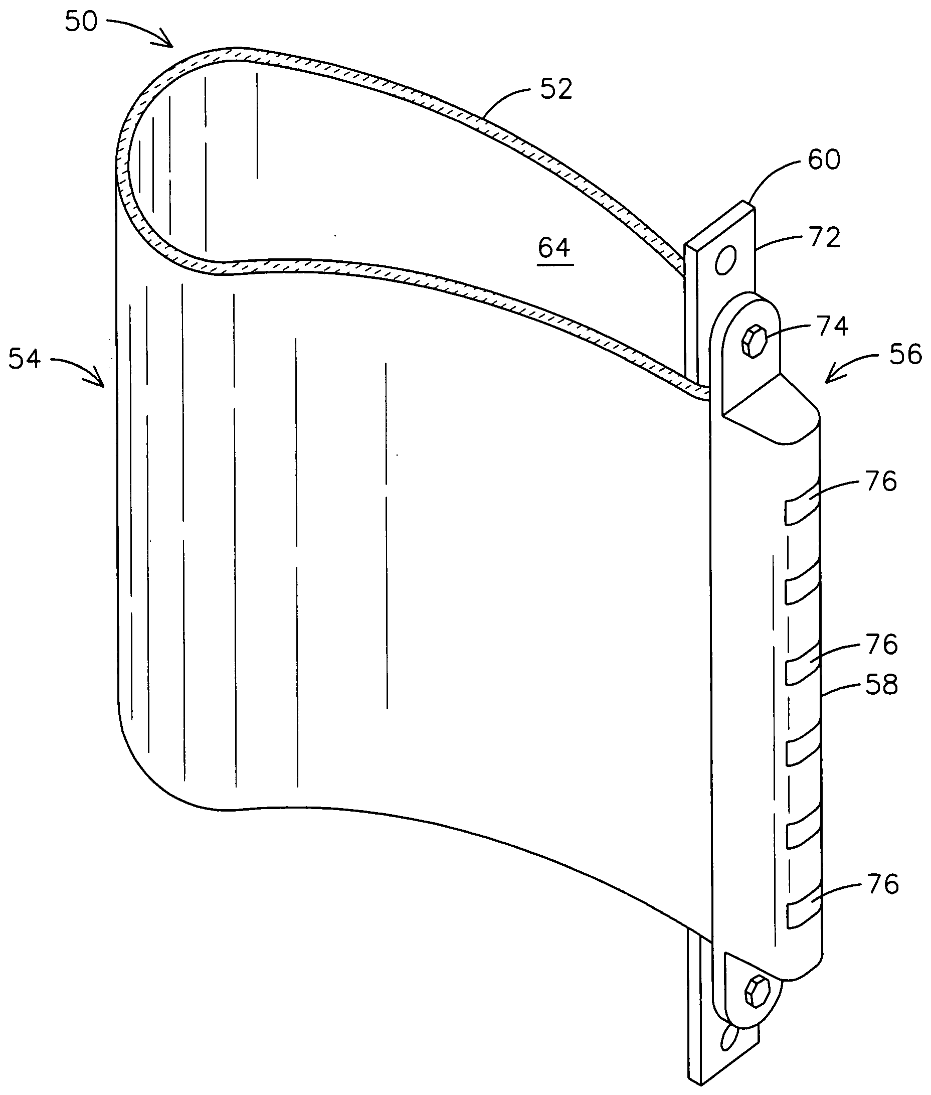
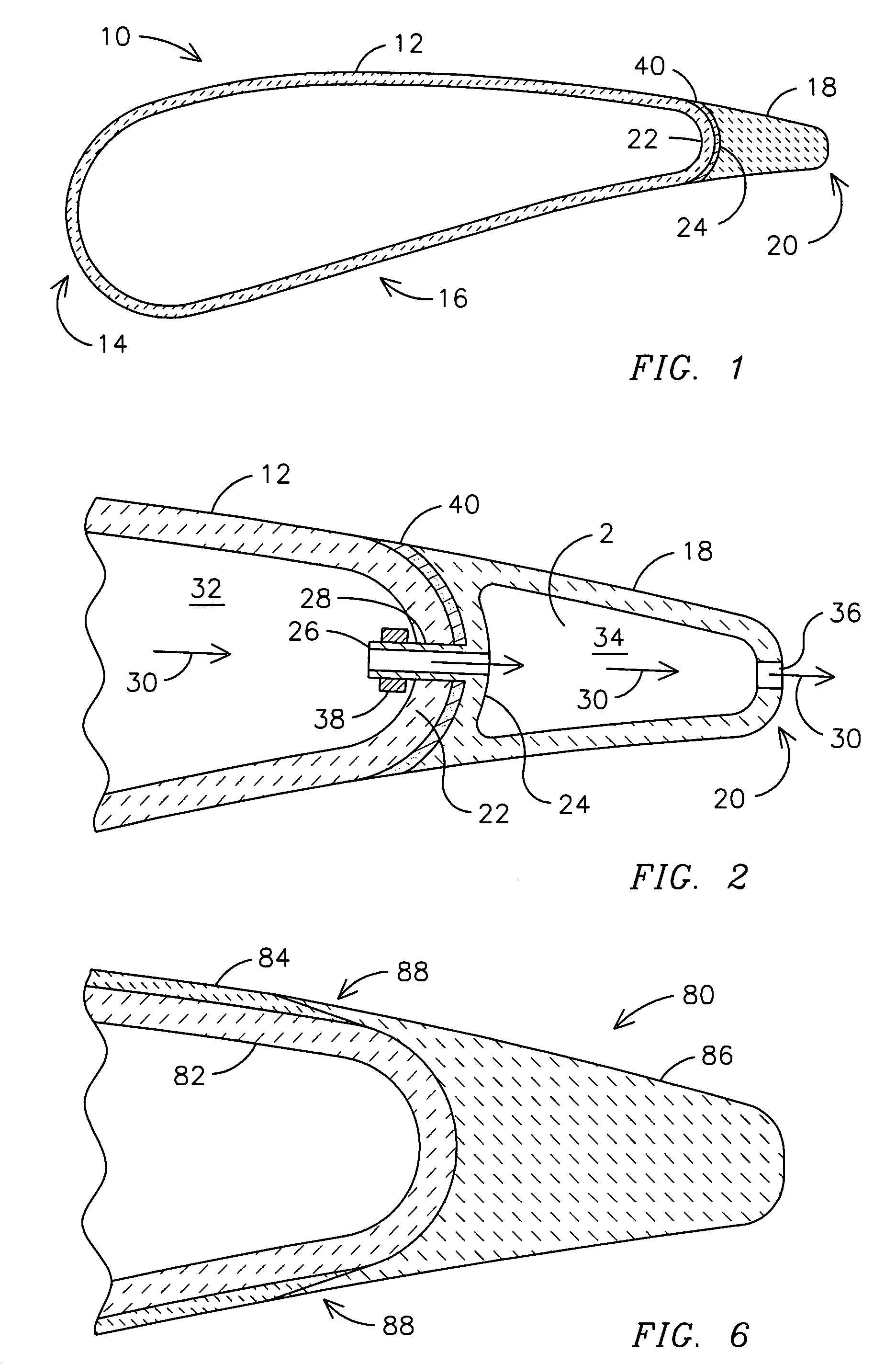
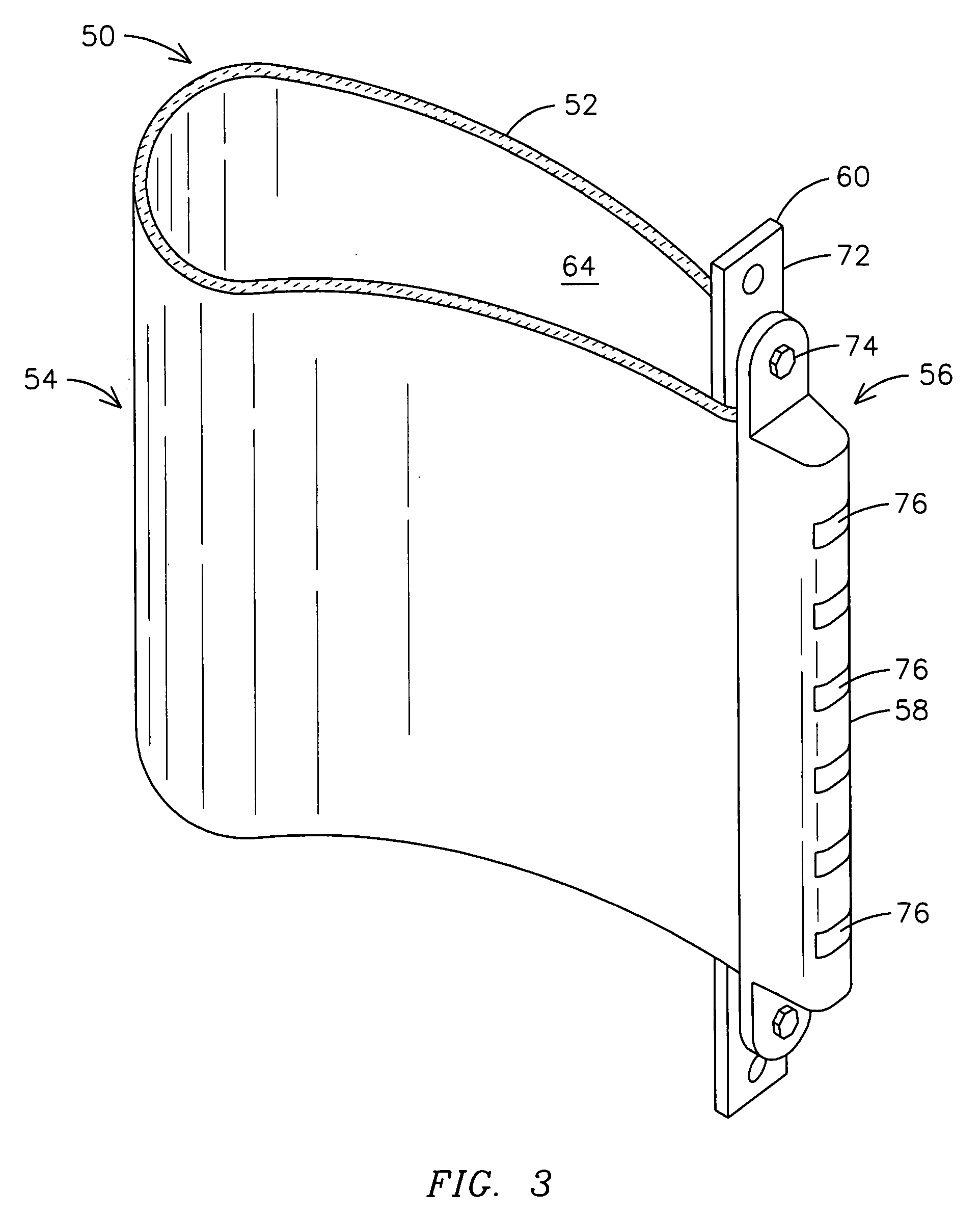
[0011]An improved airfoil 10 as may be used in a gas turbine engine is illustrated in FIG. 1. The airfoil 10 includes a ceramic matrix composite (CMC) element 12 defining a leading edge portion 14 and a chord portion 16 of the airfoil 10, and a trailing edge element 18 supported by the ceramic matrix composite element 12 and defining a trailing edge portion 20 of the airfoil. The CMC element 12 may be formed of any known type of ceramic matrix composite material as may be suitable for a particular application. The ceramic matrix composite element 12 is formed with a trailing edge attachment wall 22 having a bend radius sufficiently large to avoid damage to ceramic reinforcing fibers (not illustrated) of the wall 22. The trailing edge element 18 includes a chord attachment wall 24 configured to cooperate with the trailing edge attachment wall 22 for attachment thereto. FIG. 1 may be interpreted to represent the trailing edge element 18 being formed of a monolithic ceramic material, a...


PUM

PropertyMeasurementUnit
thicknessaaaaaaaaaa
chord lengthaaaaaaaaaa
mechanical interlockaaaaaaaaaa

Abstract

An airfoil (10) as may be used in a gas turbine engine includes a ceramic matrix composite (CMC) element (12) that extends to define a leading edge portion (14) and chord portion (16) of the airfoil, and a separately formed but conjoined trailing edge element (18) that defines a desirably thin trailing edge of the airfoil without the need for using an excessively small bend radius for reinforcing fibers in the CMC element. The trailing edge element may include a plurality of interlock elements (26) that extend through the trailing edge attachment wall (22) of the CMC element and provide mechanical attachment there between. Alternatively, the trailing edge element may be adhesively bonded or sinter bonded to the CMC element. A cooling air insert (60) may be disposed within a cooling air cavity (64) of the CMC element and may include cooling tubes (66) that extend into the trailing edge element to deliver cooling air there through.

Description

FIELD OF THE INVENTION[0001]This invention relates generally to a ceramic matrix composite airfoil such as may be used in a gas turbine engine.BACKGROUND OF THE INVENTION[0002]The design of the trailing edge of an airfoil is preferably dictated by aerodynamic considerations. For improved aerodynamic performance, it is commonly preferred to provide a thin trailing edge for a gas turbine airfoil. However, thinness may result in weakness, and there are often structural limitations that limit the trailing edge design and necessitate the use of an aerodynamic design that is less than optimal.[0003]It is known to use ceramic matrix composite (CMC) materials for airfoils and other components of gas turbine engines. CMC materials advantageously provide higher temperature capability than metal and a high strength to weight ratio. The reinforcing fibers of the CMC material are preferably wrapped around the trailing edge of an airfoil between the pressure and suction sides of the airfoil in or...

Claims


Application Information

Patent Timeline
Patent Type & Authority Applications(United States)
IPC IPC(8): B64C3/00
CPCF01D5/147F01D5/18F05D2300/603F05D2230/50F05D2300/21F01D5/284
Inventor MAZZOLA, STEFANMARINI, BONNIE
Owner SIEMENS ENERGY INC
Why Eureka
Try Eureka