Control valve for a gas direct injection fuel system

a technology of control valve and fuel system, which is applied in the direction of fuel injecting pump, machine/engine, mechanical equipment, etc., can solve the problems of limit the response of fuel supply and combustion control that can be achieved

Inactive Publication Date: 2008-08-28
DELPHI TECH INC
View PDF9 Cites 30 Cited by
  • Summary
  • Abstract
  • Description
  • Claims
  • Application Information

AI Technical Summary

Benefits of technology

[0009]In accordance with exemplary embodiments of the present invention, a control valve for a gas direct injection fuel delivery system is provided. The control valve comprises a valve body, a poppet movably received within the valve body, and an actuator disposed within the valve body. The valve body has a first fluid path, a second fluid path, and a valve seat providing fluid communication therebetween. The poppet is capable of movement between a first position and a second position. When disposed in the first position, the poppet seals the valve seat to block fluid communication between the first fluid path and the second fluid path. The poppet permits fluid communication between the first fluid path and the second fluid path as the poppet moves from the first position to the second position. The poppet is configured so that a pressure in the first fluid path produces a force that tends to move the poppet toward the second position and a pressure in the second fluid path produces a force that tends to move the poppet toward the first position. The actuator is configured to transition between an activated and a de-activated state. The actuator prevents the poppet from being disposed in the first position when in the de-activated state and the pressure in the second fluid path does not exceed the pressure in the first fluid path by at least a first pressure differential. The actuator permits the poppet to be disposed in the first position when in the activated state.

Problems solved by technology

Even with multi-port fuel injection, however, there are limits to the fuel supply response and combustion control that can be achieved.

Method used


Image

  • Control valve for a gas direct injection fuel system
  • Control valve for a gas direct injection fuel system
  • Control valve for a gas direct injection fuel system

Examples


Embodiment Construction

[0019]Exemplary embodiments of the present invention illustrated in the attached drawings relate to control valves for controlling the flow and / or pressure of fluid through a fluid path during a high-pressure fluid supply pump's fuel metering cycle. The description in the following specification relates to the exemplary embodiments illustrated in the attached drawings, but it is to be understood that the present invention is not limited to the specific embodiments disclosed herein and may assume various alternative orientations and applications. The specific devices and processes illustrated in the attached drawings and described in the following specification are simply exemplary embodiments of the inventive concepts disclosed herein. Therefore, it should be understood that specific dimensions, orientations, applications, and other physical characteristics relating to the embodiments disclosed herein are not considered to be limiting.

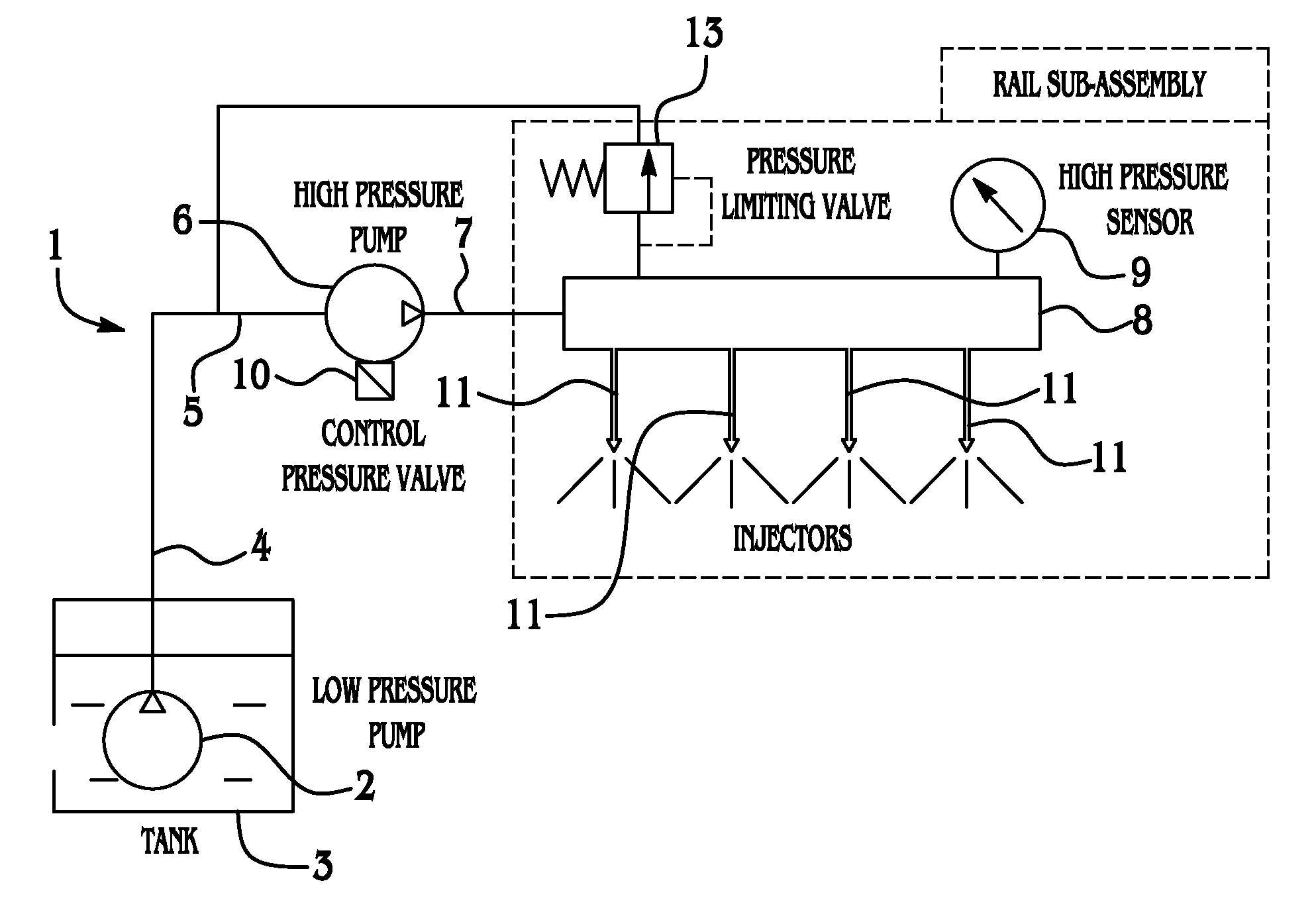
[0020]With initial reference to FIG. 1, an exemp...


PUM


Abstract

A control valve for a gas direct injection fuel delivery system is provided. The control valve comprises a valve body, a poppet movably received within the valve body, and an actuator disposed within the valve body. The valve body has a first fluid path, a second fluid path, and a valve seat providing fluid communication therebetween. The poppet is capable of movement between a first position and a second position. When disposed in the first position, the poppet seals the valve seat to block fluid communication between the first fluid path and the second fluid path. The poppet permits fluid communication between the first fluid path and the second fluid path as the poppet moves from the first position to the second position. The poppet is configured so that a pressure in the first fluid path produces a force that tends to move the poppet toward the second position and a pressure in the second fluid path produces a force that tends to move the poppet toward the first position. The actuator is configured to transition between an activated and a de-activated state. The actuator prevents the poppet from being disposed in the first position when in the de-activated state and the pressure in the second fluid path does not exceed the pressure in the first fluid path by at least a first pressure differential. The actuator permits the poppet to be disposed in the first position when in the activated state.

Description

BACKGROUND[0001]Exemplary embodiments of the present invention generally relate to fuel injection systems for internal combustion engines. More particularly, exemplary embodiments of the present invention relate to control valves for controlling the pressure and / or flow of a fluid delivered to injector valves in an engine.[0002]For many decades, gasoline internal combustion engines employed a carburetor to mix fuel with incoming air. The resulting air / fuel mixture was distributed through an intake manifold and mechanical intake valves to each of the engine cylinders. For most engines, the carburetion systems have been replaced by multi-port fuel injection systems. In a multi-port fuel injection system, there is a separate fuel injector valve that injects gasoline under pressure into the intake port at each cylinder where the gasoline mixes with air flowing into the cylinder. Even with multi-port fuel injection, however, there are limits to the fuel supply response and combustion con...

Claims


Application Information

Patent Timeline
Patent Type & Authority Applications(United States)
IPC IPC(8): F16K51/00
CPCF02M55/04F02M63/0225F02M59/367F02M2200/315F02M63/023
Inventor BURROLA, SANTOSMORENO, ALEJANDRO
Owner DELPHI TECH INC
Why Eureka
Try Eureka