Reverse flow tolerant brush seal

a brush seal and reverse flow technology, applied in the direction of engine seals, leakage prevention, machines/engines, etc., can solve the problems of reducing the support provided by the brush seal bristles, affecting the sealing effect, and presenting challenges in sealing these interfaces. permanent damage

Inactive Publication Date: 2008-08-28
RAYTHEON TECH CORP
View PDF20 Cites 8 Cited by
  • Summary
  • Abstract
  • Description
  • Claims
  • Application Information

AI Technical Summary

Benefits of technology

[0010]In accordance with the present application, a fluid seal and fluid sealing element, which are tolerant of flow direction reversals are provided. A sealing element has at least two brush stages to restrict leakage of a fluid through a gap between components to form a seal. Each brush stage includes a bristle arrangement disposed between a back plate and a common mid plate. A valve allows the fluid to bypass a bristle arrangement if the fluid pressure varies between the chambers. By allowing the higher pressure fluid to bypass one of the bristle arrangements and properly load the other bristle arrangement against a back plate, permanent damage to the sealing element is avoided.

Problems solved by technology

Sealing these interfaces presents challenges due to the excessive fluid temperatures and pressures, combined with relative axial and / or radial movement between the engine components.
Brush seal bristles are also susceptible to deflection due to fluid pressure loading.
An undesirable consequence of the side plate scallop is the reduced support it provides the bristle ends.
If a brush seal is installed in reverse or an unanticipated flow reversal occurs, the unsupported bristles will deflect under pressure.
Bristle deflections eventually yield the bristle ends, reducing their sealing effectiveness and rendering them unacceptable for continued service.
Reduced brush seal effectiveness will increase fluid leakage, engine fuel burn and, in turn, reduce an operator's profit until the brush seal is replaced.
Removal and disassembly of a gas turbine engine for brush seal replacement is both costly and time consuming.

Method used


Image

  • Reverse flow tolerant brush seal
  • Reverse flow tolerant brush seal
  • Reverse flow tolerant brush seal

Examples


Embodiment Construction

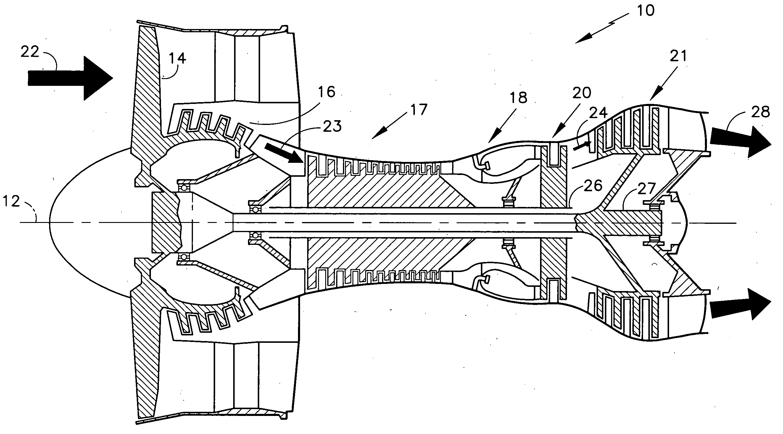
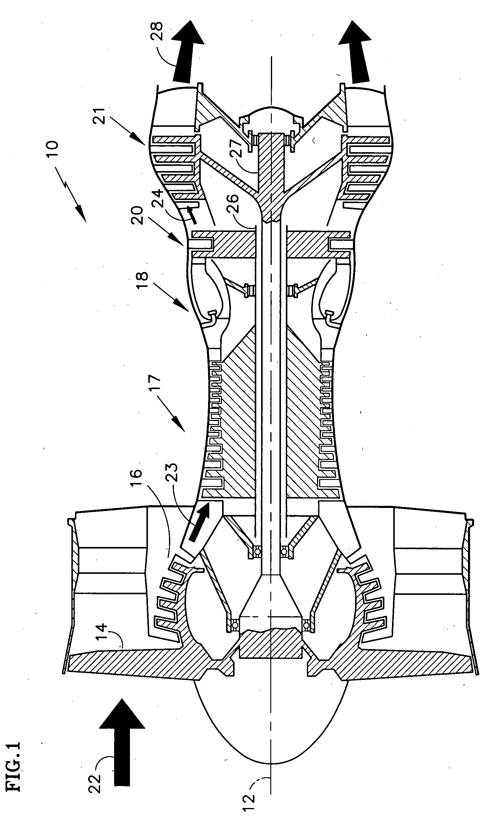
[0018]A gas turbine engine 10, such as a turbofan gas turbine engine, circumferentially disposed about a longitudinal axis or axial centerline 12, is illustrated in FIG. 1. The engine 10 includes a fan 14, low and high pressure compressor sections 16 and 17, a combustor section 18 and high and low pressure turbine sections 20 and 21. This application extends to engines with a gear driven fan, and engines with more or fewer sections. As is well known in the art, incoming ambient air 22 becomes pressurized air 23 in the compressors 16 and 17. The pressurized air 23 is mixed with fuel and burned in the combustor section 18 and combustion gases 24 expand through turbine sections 20 and 21. The turbine sections 20 and 21 drive high and low rotor shafts 26 and 27, which rotate in response to the combustion gases 24 and drive the attached compressor sections 16 and 17, and fan 14. The combustion gases 24 are finally expelled from the rear of the engine 10 as a propulsive jet 28. Seals loca...


PUM


Abstract

In accordance with the present application, a fluid seal 30 and fluid sealing element 32, which are tolerant of fluid F direction reversals are provided. A sealing element 32 has at least two brush stages 50 to restrict leakage of the fluid F through a gap 38 between a component and a sealing surface. Each brush stage 50 includes a bristle arrangement 44 sandwiched between a back plate 48 and a common mid plate 46. A value allows 70 the fluid F to bypass a bristle arrangement 44 if the fluid pressure P1 or P2 varies between the chambers. Permanent damage to the sealing element 32 is avoided by allowing the higher pressure fluid F to bypass the upstream bristle arrangement 44 and a properly load the downstream bristle arrangement against a back plate 48.

Description

BACKGROUND OF THE INVENTION[0001](1) Field of the Invention[0002]The present application relates to restricting the transfer of a fluid from between two pressurized chambers, and more specifically to a reverse flow tolerant brush seal for restricting the transfer of pressurized air between chambers in various gas turbine engine applications.[0003](2) Description of the Related Art[0004]Gas turbine engines operate according to a continuous-flow, Brayton cycle. A forward compressor section pressurizes ambient air, fuel is added and the pressurized mixture is burned in a central combustor section. The combustion gases expand through a rearward turbine section before a rearmost nozzle expels the gases as a propulsive jet. Bladed rotors in the turbine section convert thermodynamic energy from the combustion gases into mechanical energy for rotating one or more centrally mounted shafts. The shafts, in turn, drive the forward compressor section, thus continuing the cycle. Gas turbine engin...

Claims


Application Information

Patent Timeline
Patent Type & Authority Applications(United States)
IPC IPC(8): F16J15/44
CPCF16J15/3288
Inventor ADDIS, MARK E
Owner RAYTHEON TECH CORP
Why Eureka
Try Eureka