Pressure sensor

Inactive Publication Date: 2008-08-28
YAMATAKE HONEYWELL CO LTD
View PDF8 Cites 0 Cited by
  • Summary
  • Abstract
  • Description
  • Claims
  • Application Information

AI Technical Summary

Benefits of technology

[0016]With a sensor chip being made of silicon, by forming the sensor gauges in the <110> orientation having sensitivity to stress generated when pressure is applied to the diaphragm and forming the semiconductor resistors in the <100> orientation having no sensitivity to this stress, a pressure sensor can be realized having high pres

Problems solved by technology

However, in the case such as where heat is applied to a pressure sensor having this type of structure, (thermal stress) is due to the different coefficients of linear expansion among the aluminum wiring, insulating film and semiconductor resistances is generated in each of these constitutional elements, causing the zero point of the sensor output to shift.
Thus, the pressure sensor cited in JP '922 has high pressure sensitivity, but d

Method used


Image

  • Pressure sensor
  • Pressure sensor
  • Pressure sensor

Examples


Example

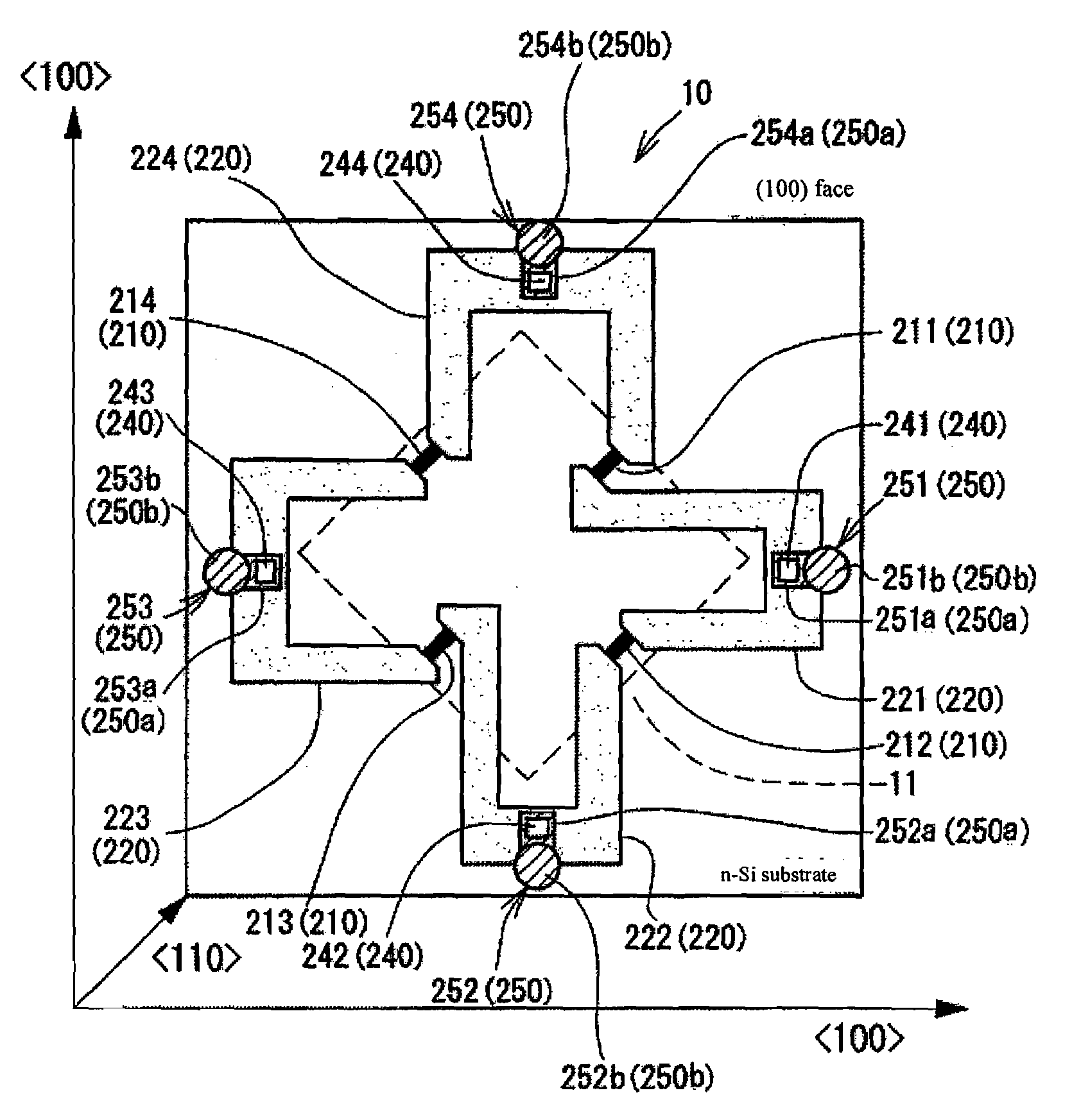
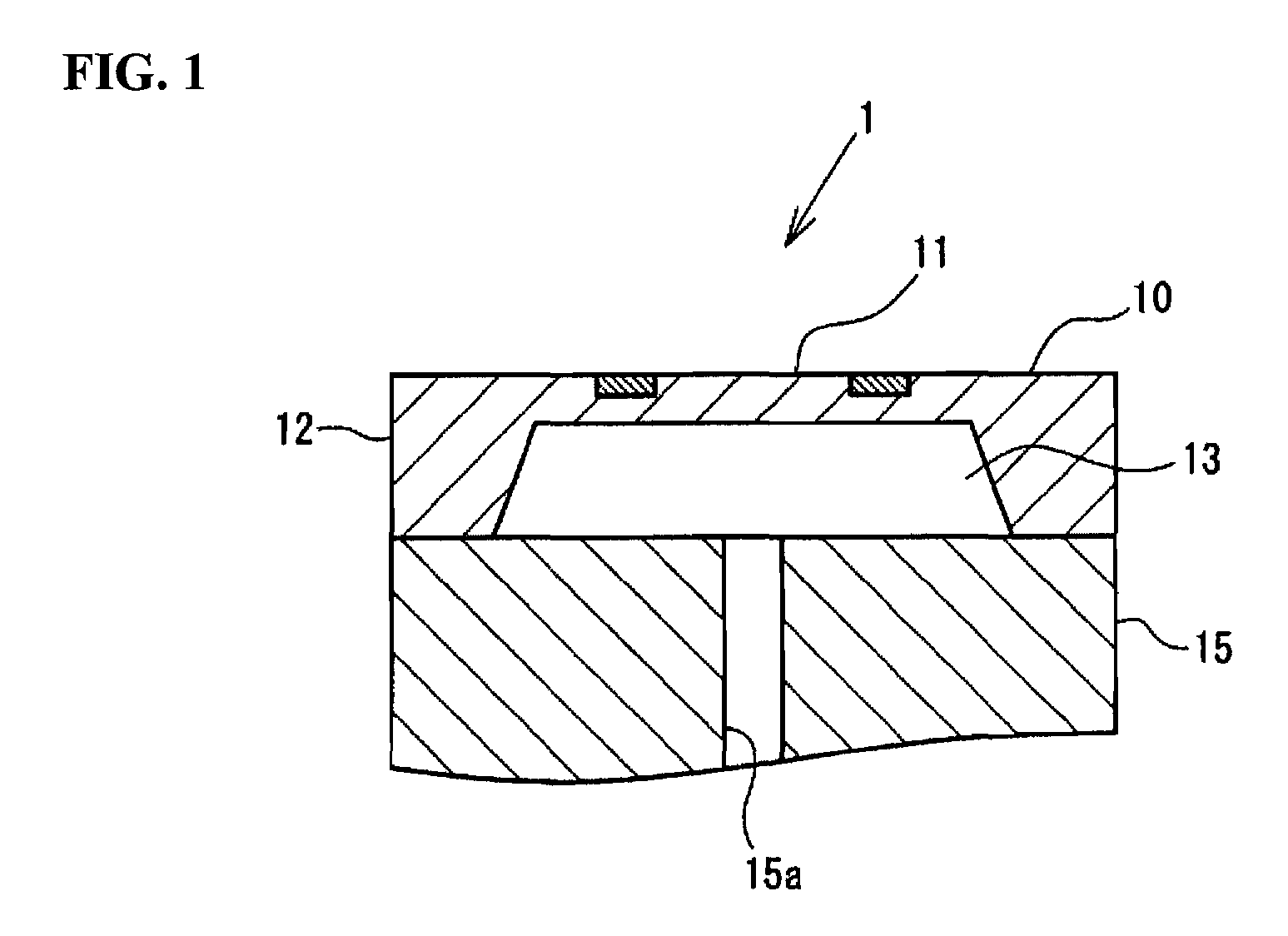
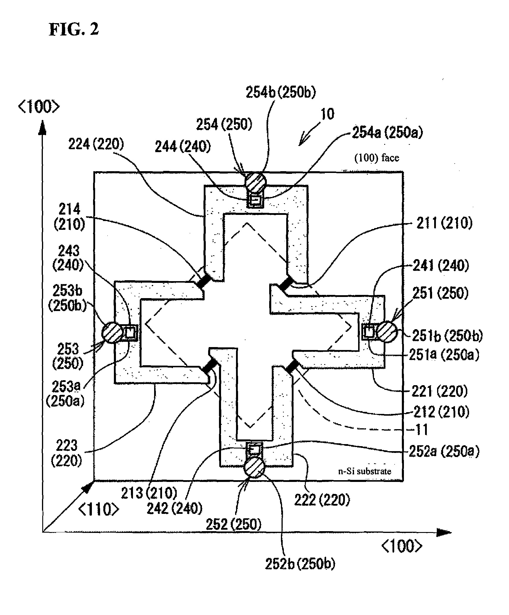
[0024]A pressure sensor 1, in an embodiment of the present invention, is described below with reference to drawings. The pressure sensor 1 in a this embodiment of the present invention has a square-shaped sensor chip 10 comprised of n-type monocrystalline Si having a (100) crystal plane orientation as is shown in FIGS. 1 and 2. Furthermore, the descriptions of the present embodiment and a subsequent embodiments use only “pressure” terminology, and needless to say, these embodiments also include the case in which different pressures are applied to both faces of the diaphragm and the pressure difference measured.

[0025]The sensor chip 10 is comprised of a square-shaped diaphragm 11 formed at a predetermined location on the chip surface and a thick-walled portion 12 forming the outer periphery of the sensor chip 10 and surrounding the diaphragm 11. Then, a square-shaped recessed portion 13 is formed at the center of the rear face of the sensor chip 10 as a result of the formation of the...


PUM


Abstract

A diaphragm is formed at a predetermined location of a sensor chip made of semiconductor material, and a sensor gauge for differential pressure or pressure sensing-use is provided on the sensor chip that includes at least the diaphragm. The sensor gauge has a plurality of sensor gauges synergistically forming a bridge circuit, and are connected to one another with semiconductor resistors, the semiconductor resistors and the sensor gauges are covered with an insulating film, and the number of contact holes, passing through a portion of the insulating film, for electrode line-out use for forming contacts electrically connected to the semiconductor resistors does not exceed the number of sensor gauges.

Description

CROSS-REFERENCE TO RELATED APPLICATION[0001]The present application claims priority under 35 U.S.C. §119 to Japanese Patent Application No. 2007-050822 filed on Feb. 28, 2007. The contents of the application is incorporated herein by reference in its entirety.TECHNICAL FIELD[0002]The present invention relates to a pressure sensor suitable for measuring absolute pressure, gauge pressure and differential pressure.BACKGROUND OF THE INVENTION[0003]For example, a pressure sensor that is widely used is comprised of a diaphragm formed over a portion of a semiconductor chip and a piezoresistive element arranged in a bridge shape on the diaphragm, and pressure on a medium to be measured is sensed by converting the displacement of the diaphragm, corresponding to the pressure on the medium to be measured, into a change in resistance of the piezoresistive element (see Japanese Unexamined Patent Application Publication No. 2002-277337 (page 2, FIG. 2) (“JP '337”), for example).[0004]In a sensor ...

Claims


Application Information

Patent Timeline
IPC IPC(8): H01C10/10
CPCG01L9/0054G01L9/04G01L9/00G01L7/08
Inventor TOJO, HIROFUMIYONEDA, MASAYUKITOKUDA, TOMOHISA
Owner YAMATAKE HONEYWELL CO LTD
Why Eureka
Try Eureka