Transparent resistance type pressure sensor and application

A resistive pressure and sensor technology, applied in instruments, electrical digital data processing, computing, etc., can solve the problems of limited application, high force sensitivity, lack of high optical transparency, etc., to avoid false sensor touch, high pressure sensitivity , the effect of high optical transparency

Pending Publication Date: 2021-04-09
RET EQUIP INC
View PDF1 Cites 1 Cited by
  • Summary
  • Abstract
  • Description
  • Claims
  • Application Information

AI Technical Summary

Problems solved by technology

This limits its use in complex gestures and commands
And most conductive voltage-sensitive composites lack high optical clarity, and/or lack long-term durability in repeated deformation
This limits its application in visual display products
[0005] CN101525469B inven

Method used


Image

  • Transparent resistance type pressure sensor and application
  • Transparent resistance type pressure sensor and application
  • Transparent resistance type pressure sensor and application

Examples


Embodiment 1

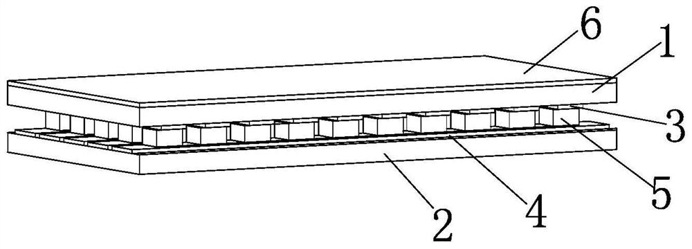
[0058] This embodiment discloses a transparent resistive pressure sensor, such as Figures 1 to 3As shown, it includes a pressure substrate 1 and a support substrate 2 arranged oppositely, and a plurality of pressure-sensitive units separated from each other are evenly distributed between the pressure substrate 1 and the support substrate 2; When the deformation occurs, the resistance changes, and when the pressure on one side of the pressure substrate 1 is removed, the resistance and shape of the pressure-sensitive unit return to the original state.

[0059] One side of the pressure substrate 1 is provided with strip-shaped first electrodes 3 arranged at intervals, and one side of the support substrate 2 is provided with strip-shaped second electrodes 4 arranged at intervals; the first electrodes 3 and the second electrodes 4 are The overlapping area of ​​one of the first electrodes 3 and one of the second electrodes 4 is provided with a pressure-sensitive film 5 to form a pr...

Embodiment 2

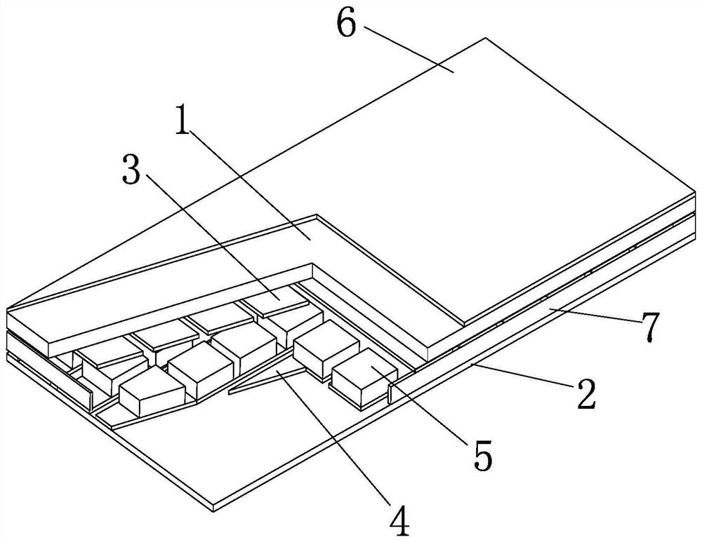
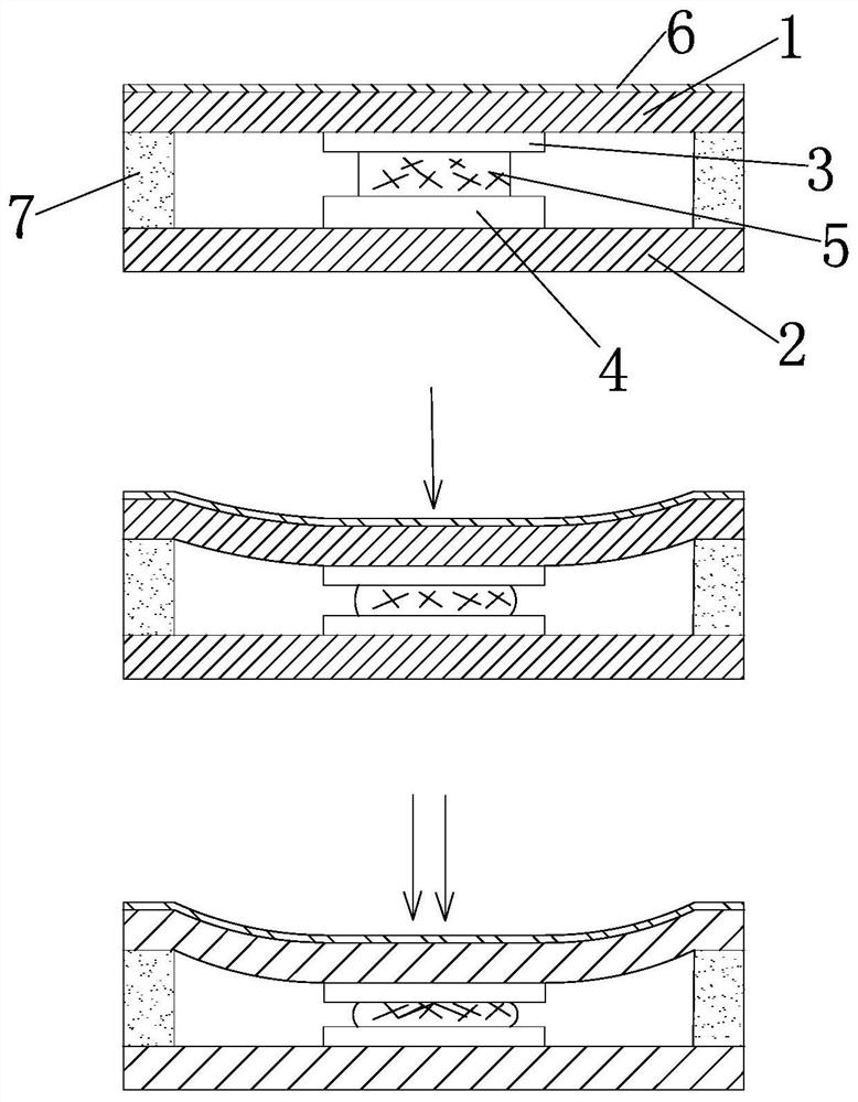
[0074] The main difference between this embodiment and embodiment 1 is detailed in Image 6 and Figure 7As shown, the pressure sensitive film 5 is located on the surface of the second electrode 4 of the pressure sensitive unit where it is located; when there is no pressure, there is an insulating gap between the pressure sensitive film 5 and the first electrode 3 .

[0075] The edges of each pressure-sensitive unit are provided with support members 7 .

[0076] The pressure sensitive film 5 in the pressure sensitive unit is attached to the surface of the second electrode 4 and there is an insulating gap between it and the first electrode 3 . When no external force is applied, no closed loop is formed between the first electrode 3 and the second electrode 4 , and the detectable resistance is infinite. Pressing the pressure substrate 1 lightly, the first electrode 3 bends downward and contacts the pressure sensitive film 5 . A closed circuit is formed between the two electro...

Embodiment 3

[0078] The main difference between this embodiment and embodiment 1 is as Figure 8 and Figure 9 As shown: the opposite sides of the pressure substrate 1 and the support substrate 2 are respectively provided with strip-shaped pressure-sensitive films 5 arranged at intervals; The pressure-sensitive film 5 on one side is arranged orthogonally; the pressure-sensitive film 5 on one side of each pressure substrate 1 and the pressure-sensitive film 5 on one side of a support substrate 2 overlap each other to form the pressure-sensitive unit;

[0079] When the pressure-sensitive film 5 is under pressure, it undergoes elastic deformation to cause a change in resistance, and when it is not under pressure, the shape of the pressure-sensitive film 5 returns to the initial state, causing the resistance to return to the initial state.

[0080] When one side of the pressure substrate 1 is not under pressure, there is an insulating gap between the pressure-sensitive film 5 on the side of t...


PUM

PropertyMeasurementUnit
Storage modulusaaaaaaaaaa
Thicknessaaaaaaaaaa

Abstract

The invention discloses a transparent resistance type pressure sensor. The sensor comprises a pressure substrate and a support substrate which are oppositely arranged, and a plurality of mutually separated pressure-sensitive units are uniformly distributed between the pressure substrate and the support substrate; each pressure-sensitive unit comprises a pressure-sensitive film, and the pressure-sensitive film comprises an optically transparent elastic polymer and conductive nanoparticles; the nanoparticles are distributed on the surface and inside of the elastic polymers and are reticular, and at least one conductive channel is formed; the pressure-sensitive units deform to cause resistance change when being subjected to pressure applied to one side of the pressure substrate, and when the pressure on one side of the pressure substrate is removed, the resistance and the shape of the pressure-sensitive units are restored to the initial state. The invention further discloses an electronic system applying the transparent resistance type pressure sensor to multi-point touch detection hardware and software. The pressure sensor is sensitive to pressure and good in use durability.

Description

technical field [0001] The invention relates to the technical field of resistive pressure sensors, in particular to a transparent resistive pressure sensor and its application. Background technique [0002] A touch panel is an input device that allows a user to input information through physical contact with the panel device. Touch panels are commonly used as input devices for various products such as home appliances, televisions, notebook computers and monitors and portable electronic devices such as notebook computers, e-books, portable multimedia players, GPS navigation units, super mobile computers, smartphones, smart watches, tablets, and mobile communication terminals. [0003] The most commonly used touch panel technologies can be classified into capacitive and resistive. Traditional capacitive touch panels are known for sensing the location of a touch, but lack the ability to accurately detect pressure being applied to the device. Resistive-based touchpads can pro...

Claims


Application Information

Patent Timeline
IPC IPC(8): G06F3/041G06F3/044
CPCG06F3/0412G06F3/0445
Inventor 邱雨胡忠营
Owner RET EQUIP INC
Why Eureka
Try Eureka