Image processing system, image processing method, and image processing program product

a technology of image processing and image pickup, applied in the field of image processing system, image processing method, image processing program product, can solve the problems of reducing the precision of coring processing, not ensuring high-precision correction, and dynamic fluctuation of noise arising from image pickup devi

Active Publication Date: 2008-08-28
EVIDENT CORP
View PDF10 Cites 19 Cited by
  • Summary
  • Abstract
  • Description
  • Claims
  • Application Information

AI Technical Summary

Problems solved by technology

In general, digital signals thus outputted from the A / D converter of such a digital image pickup device contain various noise components.
However, the noise arising due to the image pickup device can dynamically fluctuate due to various factors such as the image signal level, the gain thereof, the temperature of the image pickup device when the image is acquired, etc.
In some cases, this leads to reduction in the precision of the coring processing results.
Accordingly, such a technique does not ensure high-precision correction.
This leads to a reduction in the precision of the edge component extraction.
Accordingly, for the above-described reason, such a technique has a problem of poor correction precision.
Therefore, for the above-described reason, such a technique also has a problem of poor correction precision.
Accordingly, such a technique has a problem of performing the noise reduction processing and the edge extraction processing without mutual cooperation.

Method used


Image

  • Image processing system, image processing method, and image processing program product
  • Image processing system, image processing method, and image processing program product
  • Image processing system, image processing method, and image processing program product

Examples


embodiment 1

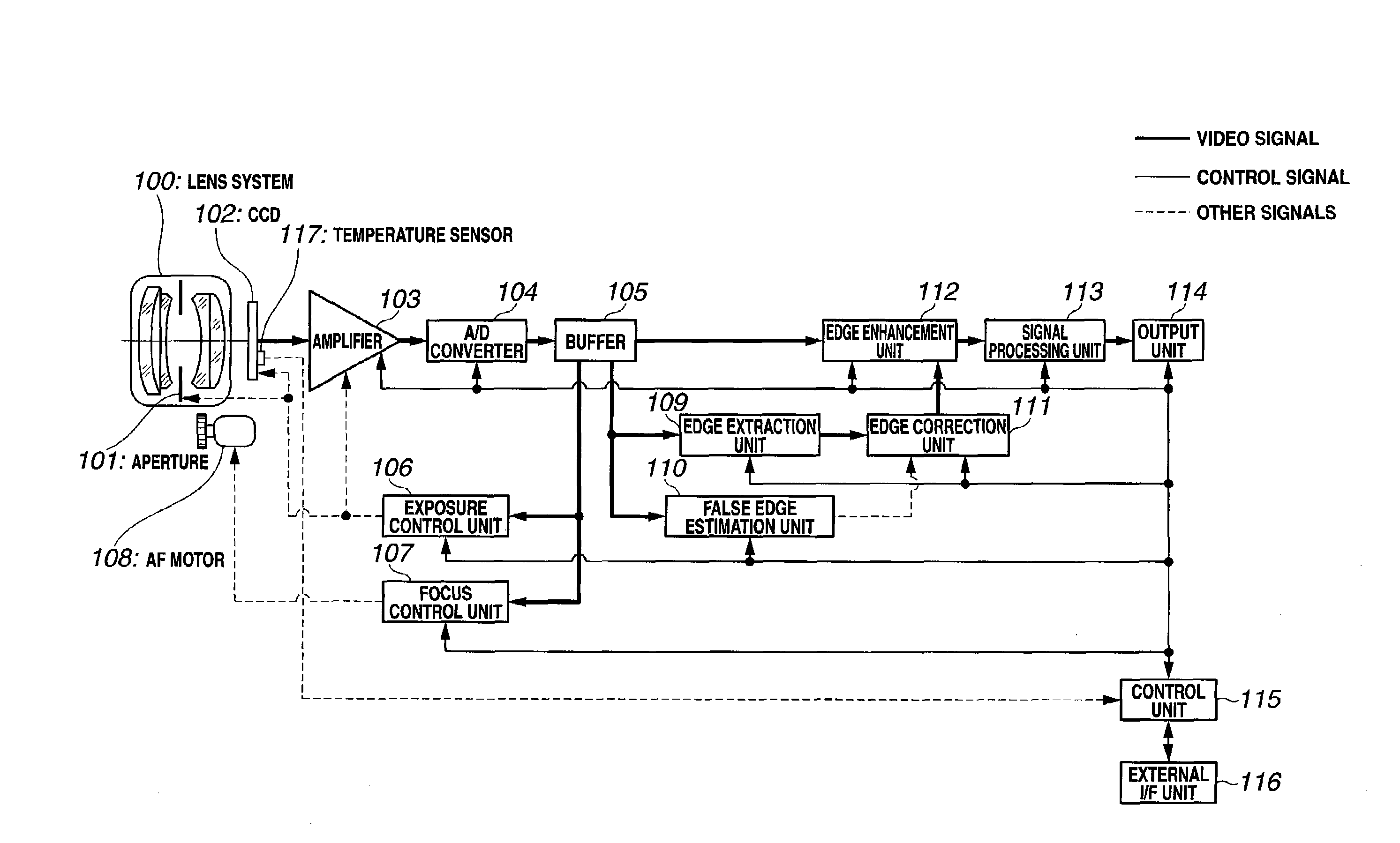
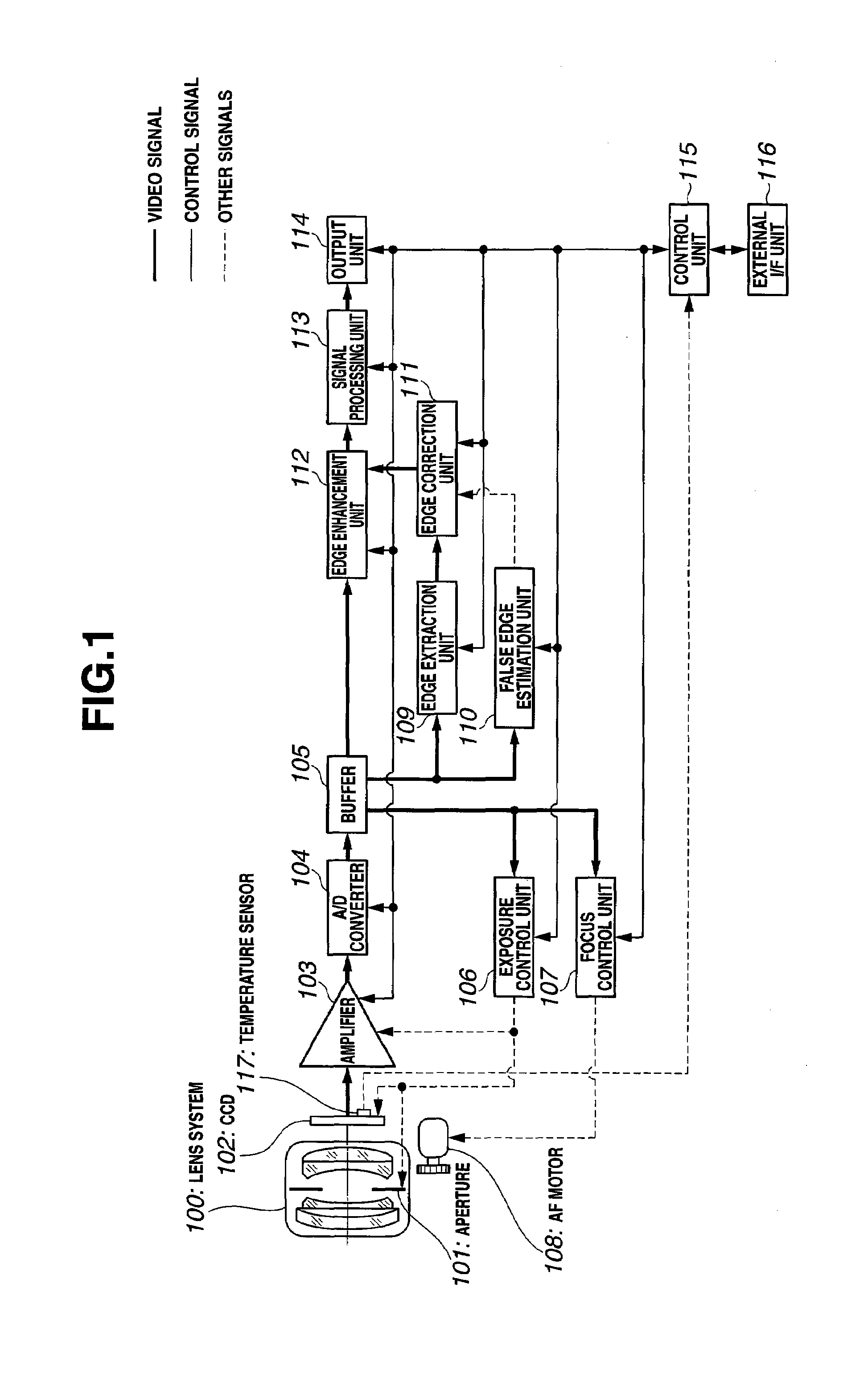
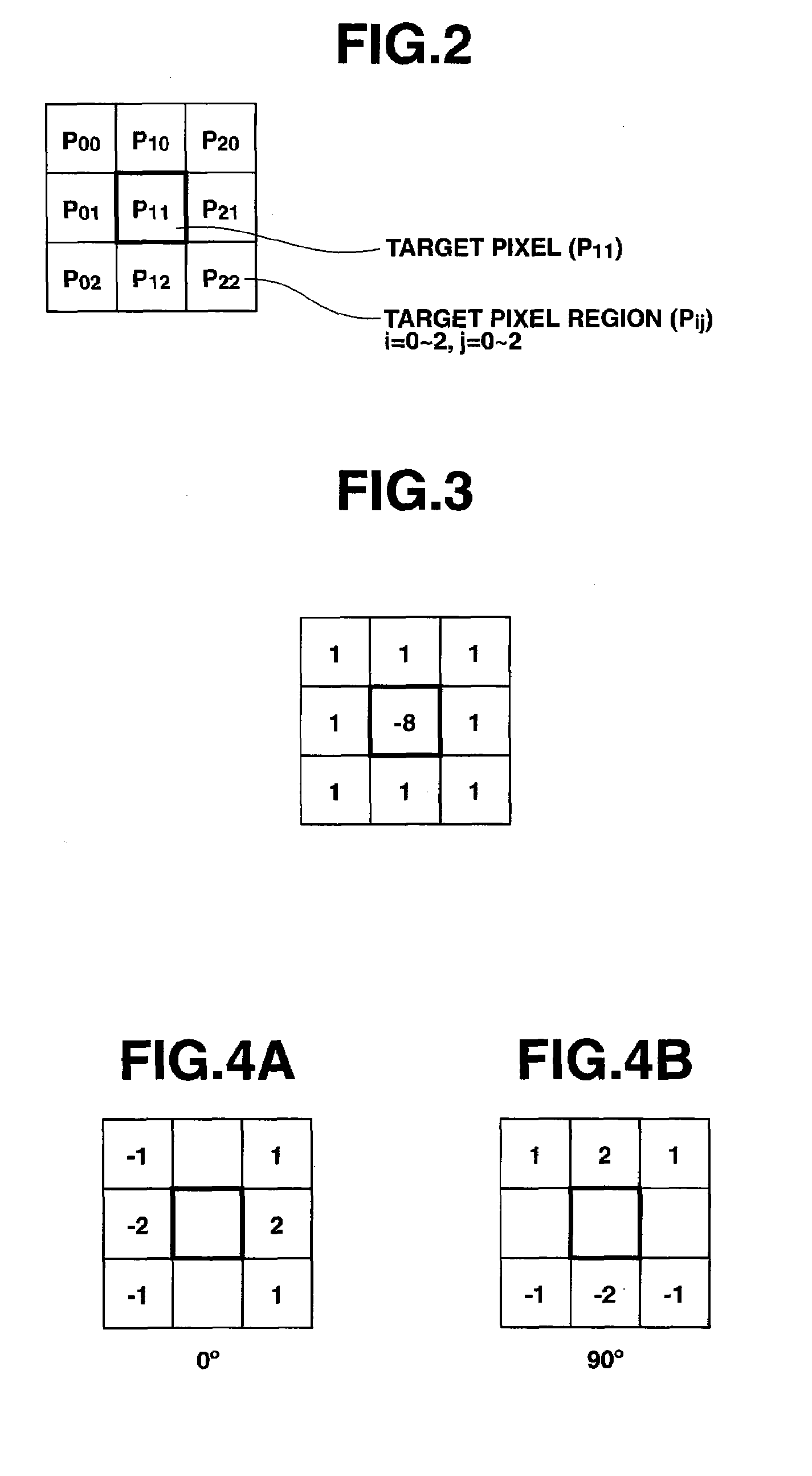
[0060]FIG. 1 through FIG. 15 show an embodiment 1 of the present invention. FIG. 1 is a block diagram which shows a configuration of an image processing system. FIG. 2 is a diagram which shows a structure of a target region which is 3×3 pixels in area and which is used for edge extraction processing. FIG. 3 is a diagram which shows a structure of an isotropic edge extraction filter applicable to the 3×3 pixel size target region. FIG. 4A and FIG. 4B show the structures of a horizontal edge extraction filter and a vertical edge extraction filter applicable to the 3×3 pixel size target region. FIG. 5 shows a block diagram which shows a configuration of a false edge estimation unit. FIG. 6 is a line graph which shows the relation between the amount of noise and the signal level. FIG. 7 is a line graph which shows the relation between the amount of noise and the false edge signal. FIG. 8 is a line graph for describing the edge model. FIG. 9 is a line graph for describing the calculation ...

embodiment 2

[0188]FIG. 16 through FIG. 24 show an embodiment 2. Specifically, FIG. 16 is a block diagram which shows a configuration of an image processing system. FIG. 17 is a block diagram which shows a configuration of a noise processing unit. FIG. 18 is a block diagram which shows an example of the configuration of a false edge estimation unit. FIG. 19 is a block diagram which shows another example of the configuration of the false edge estimation unit. FIG. 20 is a block diagram which shows a configuration of an edge correction unit. FIG. 21 is a line graph which shows the response of the coring processing performed by the edge correction unit. FIG. 22 is a flow chart which shows the overall flow of the signal processing according to an image processing program. FIG. 23 is a flow chart which shows the detailed noise processing performed in Step S30 shown in FIG. 22. FIG. 24 is a flow chart which shows the detailed processing for estimating the false edge in Step S31 shown in FIG. 22.

[0189]...

embodiment 3

[0278]FIG. 25 through FIG. 33 show an embodiment 3 according to the present invention. Specifically, FIG. 25 is a block diagram which shows a configuration of an image processing system. FIG. 26 is a diagram which shows a pattern of a Bayer-type primary color filter. FIG. 27 is a diagram which shows a pattern of a color-difference line-sequential complementary color filter. FIG. 28 is a block diagram which shows an example of the configuration of the false edge estimation unit. FIG. 29 is a bloc diagram which shows another example of the configuration of the false edge estimation unit. FIG. 30 is a block diagram which shows a configuration of the edge correction unit. FIG. 31A, FIG. 31B, FIG. 31C show line graphs each of which shows an example of the response in the coring processing. FIG. 32 is a flow chart which shows the overall flow of the signal processing according to an image processing program. FIG. 33 is a flow chart for making a detailed description of the false edge estim...


PUM


Abstract

An image processing system including: a CCD which outputs an image signal; an edge extraction unit which extracts an edge signal from the image signal; a false edge estimation unit which estimates an edge signal that arises due to noise components based upon the image signal; an edge correction unit which corrects the edge signal by performing coring processing based upon the edge signal that arises due to noise components; and an edge enhancement unit which performs enhancement processing on the image signal based upon the edge signal thus corrected.

Description

CROSS REFERENCE TO RELATED APPLICATION[0001]This application is a continuation application of PCT / JP2006 / 318967 filed on Sep. 25, 2006 and claims benefit of Japanese Application No. 2005-311704 filed in Japan on Oct. 26, 2005, the entire contents of which are incorporated herein by this reference.BACKGROUND OF THE INVENTION[0002]1. Field of the Invention[0003]The present invention relates to an image processing system, image processing method, and an image processing program product for extracting edge signals from an image signal acquired by an image pickup device.[0004]2. Description of the Related Art[0005]In general, digital image pickup devices such as digital cameras, digital video cameras, etc., comprise an image pickup device, an analog circuit which performs various kinds of analog processing for an analog signal outputted from the image pickup device, and an A / D converter which converts the signal outputted from the analog circuit into a digital signal.[0006]In general, di...

Claims


Application Information

Patent Timeline
Patent Type & Authority Applications(United States)
IPC IPC(8): H04N5/235H04N5/217H04N5/357
CPCG06K9/4609G06T7/0085H04N5/142H04N5/208G06T2207/20192H04N9/045G06T5/002G06T5/003G06T2207/10024H04N5/357G06T7/13G06V10/443H04N25/60H04N23/843H04N25/136H04N25/134
Inventor TSURUOKA, TAKAO
Owner EVIDENT CORP
Why Eureka
Try Eureka