
Optical modulator

a modulator and optical technology, applied in the field of optical modulators, can solve the problems of degrading the optical characteristics of the optical modulator, difficult to accurately detect radiation-mode light, and difficult to separate radiation-mode light from radiation-mode mismatching, so as to effectively extract the output light from the main output waveguide, suppress the generation of radiation-mode light, and achieve the effect of stably removing radiation-mode ligh

Active Publication Date: 2012-02-02
SUMITOMO OSAKA CEMENT CO LTD
View PDF11 Cites 11 Cited by
  • Summary
  • Abstract
  • Description
  • Claims
  • Application Information

AI Technical Summary

Benefits of technology

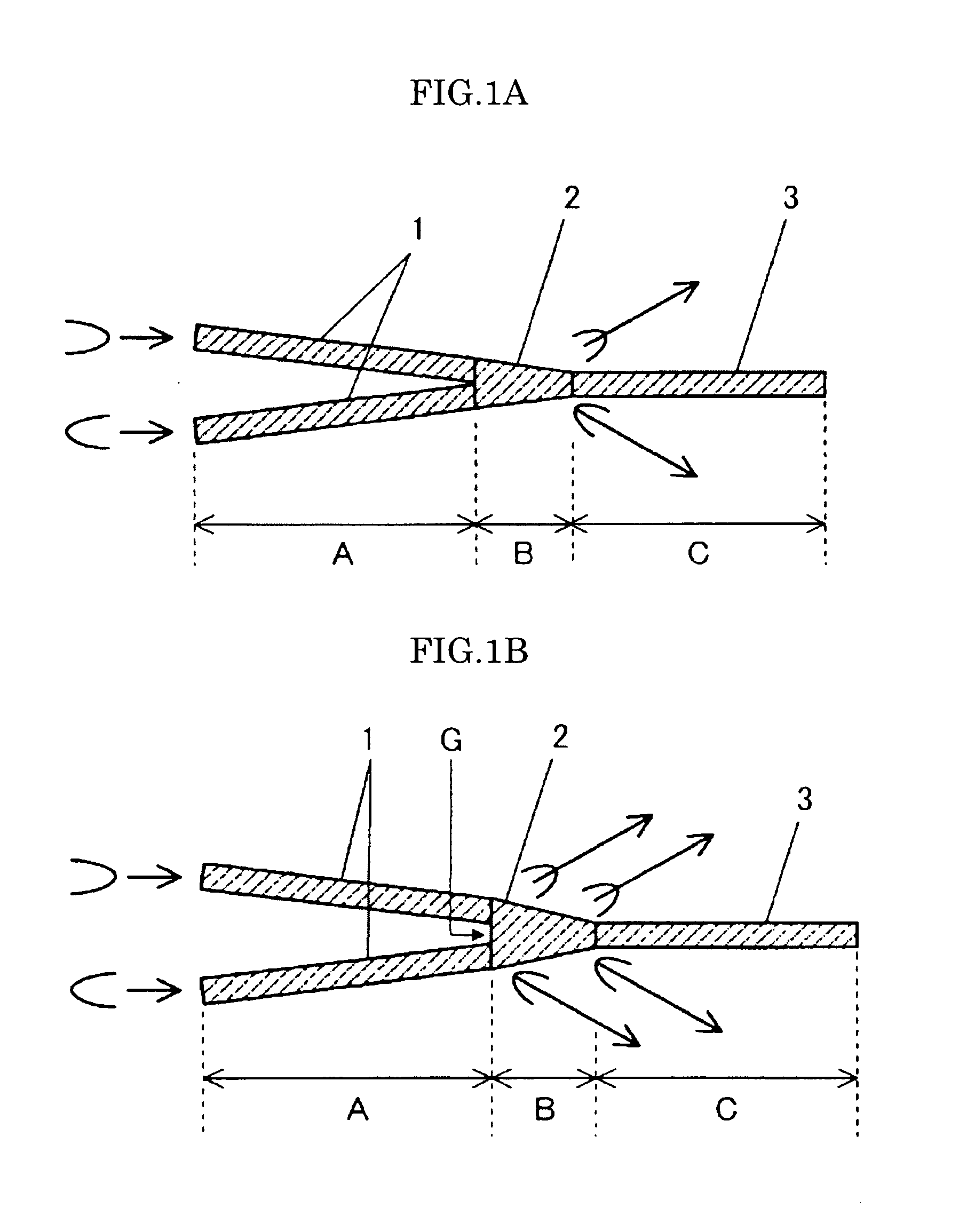
[0020]According to claim 1 of the invention, there is provided an optical modulator having a Mach-Zehnder type waveguide on a surface of a dielectric substrate, wherein a waveguide after multiplexing in a Y-multiplexer in an output side of the Mach-Zehnder type waveguide is a multiple mode waveguide, and a subsidiary output waveguide as a high-order mode waveguide is connected to a portion where the multiple mode waveguide is changed to a main output waveguide as a single mode waveguide. Therefore, since there is no region (single mode waveguide) where the mode rarely changes or leakage is generated in the portion where the two branching waveguides are coupled, it is possible to suppress generation of the mode mismatching light. Furthermore, since the multiple mode waveguide has a length equal to or longer than 150 μm, the mode mismatching light generated in the coupling portion of the two branching waveguides is rarely recombined with the main output waveguide or the subsidiary output waveguide in the sense of a distance, and the mode mismatching light is rarely mixed with the radiation-mode light or the output light.
[0021]According to claim 2 of the invention, the two subsidiary output waveguides are arranged axisymmetrically with respect to the main output waveguide by interposing the main output waveguide therebetween. Therefore, it is possible to stably extract the radiation-mode light using the subsidiary output waveguide.
[0022]According to claim 3 of the invention, a width of each of two branching waveguides coupled in the Y-multiplexer is narrower than a width of the main output waveguide, and a width of the subsidiary output waveguide is narrower than a width of the branching waveguide. Therefore, it is possible to approximately match the mode diameter in the coupling portion of the branching waveguide and the mode diameter of the main output waveguide as the single mode waveguide where the light waves are output in the turned-on state. As a result, it is possible to effectively extract the output light from the main output waveguide.
[0023]According to claim 4 of the invention, a thickness of the dielectric substrate is equal to or smaller than 20 μm. Therefore, since the effect of the mode mismatching light is significantly exhibited, it is necessary to suppress the mode mismatching light. For this reason, by applying the configuration of the optical modulator of the invention, it is possible to reduce a drive voltage for driving the optical modulator, match velocities of the drive signal and the propagating light, and suppress the mode mismatching light.
[0024]According to claim 5 of the invention, a high-order mode waveguide divided from the input waveguide is provided in the middle of the input waveguide before reaching a Y-splitter in an input side of the Mach-Zehnder type waveguide. Therefore, since the high-order mode light generated in the light input portion and propagating through the input waveguide can be removed from the high-order mode waveguide, it is possible to approximate the dividing ratio of the light waves in the Y-splitter to 1:1. If the dividing ratio is not 1:1, a high-order mode is generated in the Y-multiplexer regardless of the modulation. Such undesired light is mixed with the main output waveguide or the subsidiary output waveguide so as to degrade characteristics of the extinction ratio. By adding the high-order mode waveguide to the input portion, it is possible to further suppress a generation ratio of undesired light.

Problems solved by technology

The mode mismatching light causes degradation of optical characteristics of the optical modulator.
Particularly, because of increasing propagation loss and degradation of an extinction ratio, or since the mode mismatching light interferes with the radiation-mode light, or the mode mismatching light itself is detected by monitoring means, it is disadvantageously difficult to accurately detect the radiation-mode light.
However, as disclosed in PTL 4, since the light waves leaking from the optical waveguide propagate through the thinned dielectric substrate while they are constricted within the substrate, it is difficult to separate the radiation-mode light from the mode mismatching light and, in some cases, it is also difficult to separate the signal light from the radiation-mode light.
However, in the configuration of the 2×3 branching waveguide disclosed in PTL 4, problematically, a part of the mode mismatching light generated when two branching waveguides are combined may be recombined with the optical waveguide and mixed with the radiation-mode light or the output light.

Method used


Image

  • Optical modulator
  • Optical modulator
  • Optical modulator

Examples


Embodiment Construction

[0031]Hereinafter, the optical modulator of the invention will be described in detail.

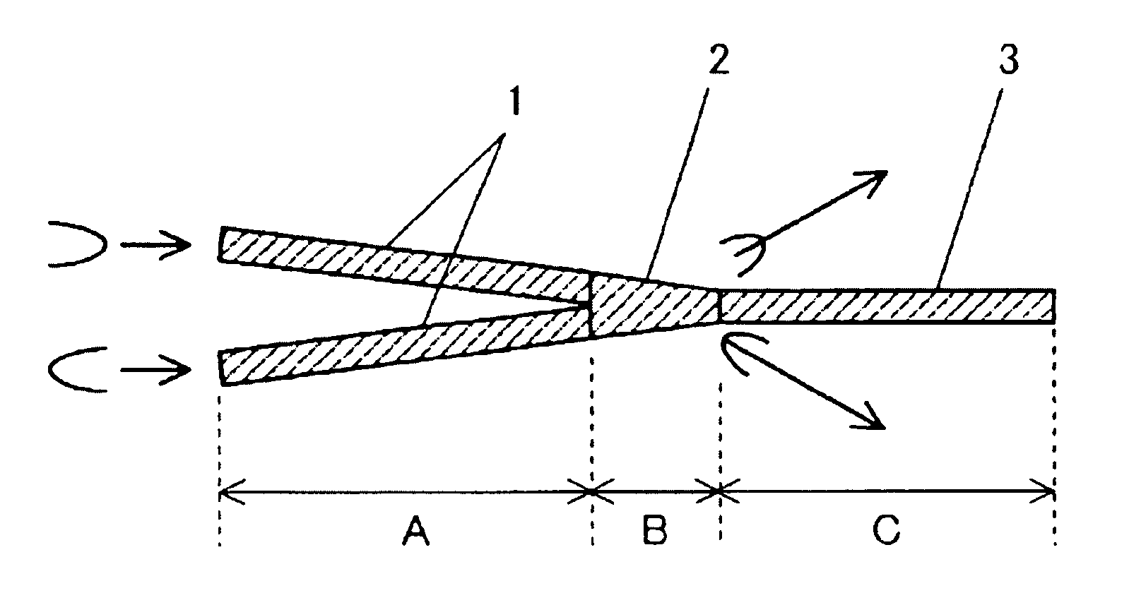
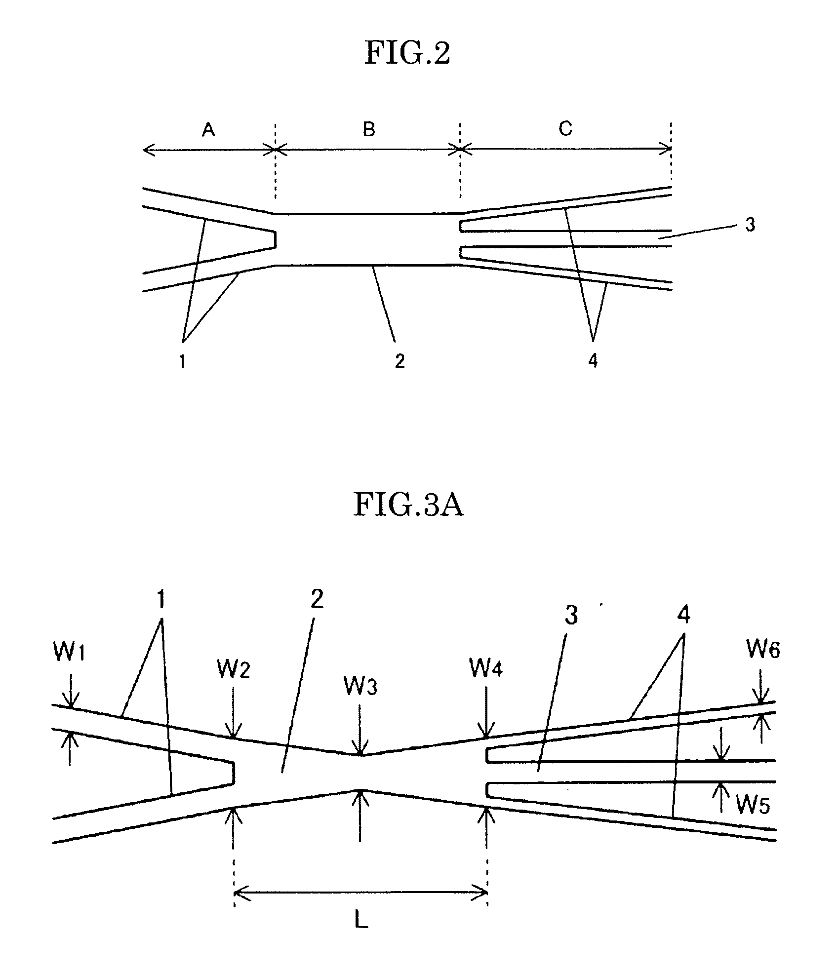
[0032]FIG. 2 is a diagram illustrating a waveguide shape in the vicinity of the Y-multiplexer used in the optical modulator of the invention.

[0033]The invention is characterized in that, in the optical modulator having a Mach-Zehnder type waveguide on the surface of the dielectric substrate, the waveguide 2 obtained after multiplexing using the Y-multiplexer in the output side of the Mach-Zehnder type waveguide is a multiple mode waveguide, and a subsidiary output waveguide 4 as a high-order mode waveguide is connected to a portion (the boundary between regions B and C) where the multiple mode waveguide 2 is changed to a main output waveguide 3 as a single mode waveguide. The reference numeral 1 denotes, as an arm of the MZ-type waveguide, two branching waveguides coupled in the Y-multiplexer.

[0034]The light intensity Pc of the output light of the optical modulator and the light intensity P± of the...


PUM

PropertyMeasurementUnit
lengthaaaaaaaaaa
thicknessaaaaaaaaaa
thicknessaaaaaaaaaa

Abstract

In order to provide an optical modulator capable of suppressing generation of mode mismatching light in the Y-multiplexer in the MZ-type waveguide or mixing of the mode mismatching light with the radiation-mode light or the output light, and separately extracting output light and radiation-mode light, there is provided an optical modulator having a Mach-Zehnder type waveguide on a surface of a dielectric substrate, wherein a waveguide after multiplexing in a Y-multiplexer in an output side of the Mach-Zehnder type waveguide is a multiple mode waveguide 2, a subsidiary output waveguide as a high-order mode waveguide 2 is connected to a portion where the multiple mode waveguide is changed to a main output waveguide 3 as a single mode waveguide, and the multiple mode waveguide 2 has a length equal to or longer than 150 μm.

Description

TECHNICAL FIELD[0001]The present invention relates to an optical modulator, and more particularly, to an optical modulator having a Mach-Zehnder type waveguide on a surface of an dielectric substrate.BACKGROUND ART[0002]In the fields of optical communication or optical measurement, optical waveguide elements having optical waveguides on a surface of an dielectric substrate are widely used. Among the optical waveguide elements, an optical modulator having a Mach-Zehnder type waveguide to perform optical modulation such as light intensity modulation is widely used due to advantages such as readiness of integration and high efficient optical modulation.[0003]In the optical modulator having the Mach-Zehnder type waveguide (hereinafter, referred to as a “MZ-type waveguide”), an electric field is applied to at least an arm (branching waveguide) in the MZ-type waveguide to control phases of the light waves propagating through the corresponding arm. In addition, the LiNbO3 substrate is apt ...

Claims


Application Information

Patent Timeline
Patent Type & Authority Applications(United States)
IPC IPC(8): G02F1/035
CPCG02B6/125G02B6/29352G02F2001/217G02F1/3136G02F2001/212G02F1/225G02F1/3137G02F1/212G02F1/217G02B6/2813
Inventor KONDOU, KATSUTOSHIOIKAWA, SATOSHISUGAMATA, TORU
Owner SUMITOMO OSAKA CEMENT CO LTD
Learn More