
Printer and Control Method for the Same

Inactive Publication Date: 2008-08-28
SEIKO EPSON CORP
View PDF6 Cites 8 Cited by
  • Summary
  • Abstract
  • Description
  • Claims
  • Application Information

AI Technical Summary

Benefits of technology

[0018]A printer according to the present invention that writes to the print buffer and executes the printing and paper transportation process while receiving image data from a host computer enables printing continuously and eliminating unwanted white stripes in the printed output by desirably balancing the speed of the paper transportation and printing process with the speed of the conversion process.
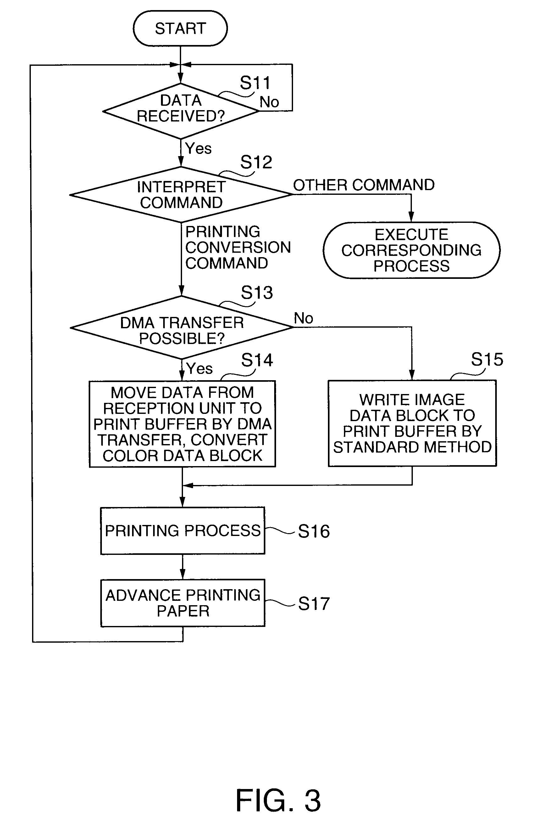
[0023]The invention thus determines if color block data for a plurality of colors can be directly transferred to the image conversion unit based on the conversion format information contained in a single convert and print command, and transfers the image data directly to the image conversion unit without first buffering the data to the receive buffer if direct transfer is determined possible. Compared with sending the color block data separately for each color, first receiving the data into the receive buffer each time a command and color block data are received, interpreting the command, and then converting the data in the image conversion unit as in the related art, the method of the invention reduces the number of times commands are interpreted, and can complete the DMA transfer once it starts without interruption between the color data blocks. The conversion process to the image conversion unit can therefore be accelerated, the speed of the paper feed and printing process and the speed of the conversion process can be balanced more desirably than in the related art, and printing can run continuously. A clean printout free of white stripes between image blocks can thus be achieved.

Problems solved by technology

This results in a time-consuming reception and conversion process when printing large image data files and thus lowers printing process speed.
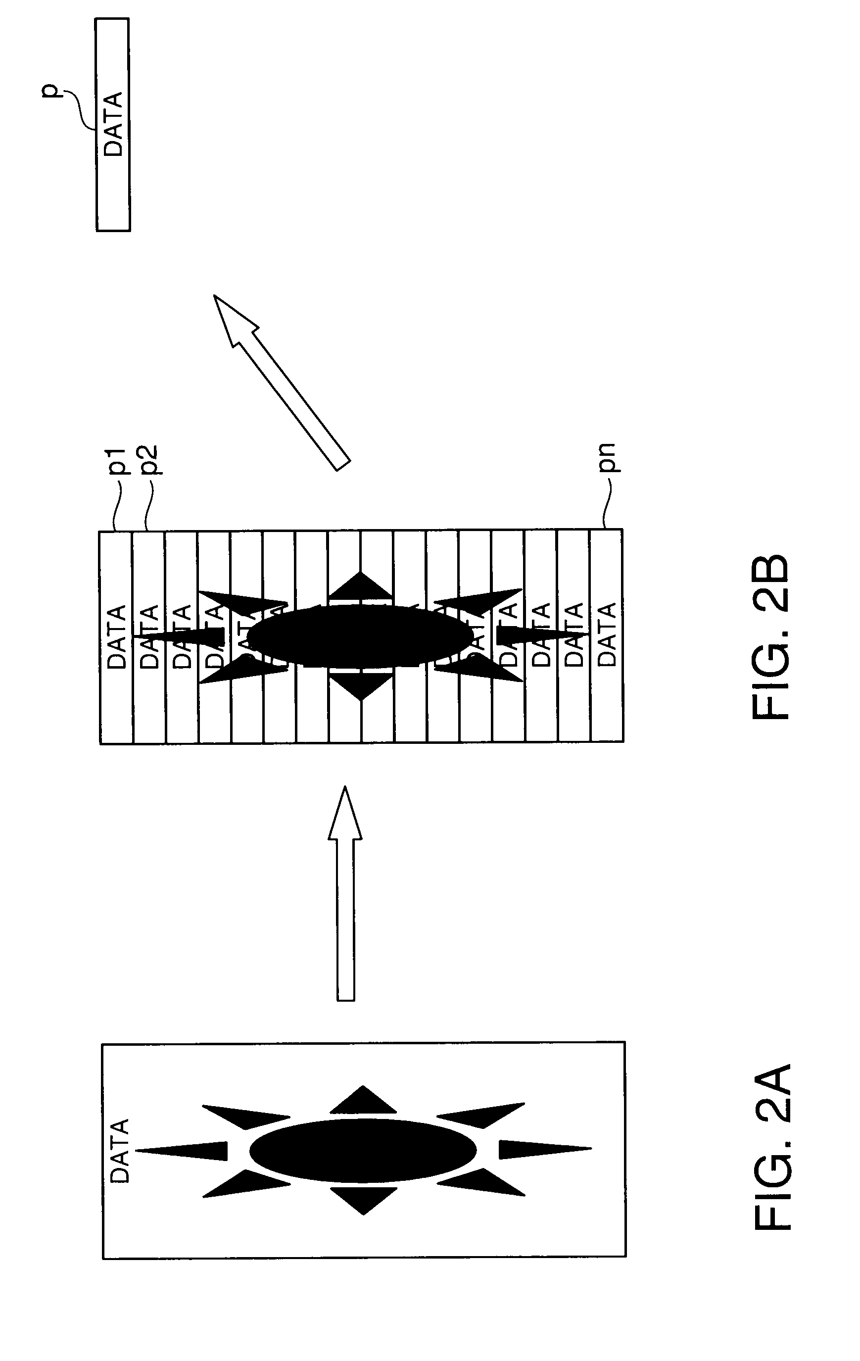
Executing this operation for each of the five color data blocks A to E means that 25 command interpreting and evaluation operations are executed in the conversion process for printing image data P. Numerous command interpretations necessarily reduces conversion process speed, and thus lead to a drop in printing process speed.
If the balance between the printing speed and the conversion process speed is poor, the speed of the overall printing process drops.
These white bands a to d occur because the large number of command interpretations executed by the command interpreter slows the conversion process, causing an imbalance with the printing speed (including paper transportation and printing) and thus preventing continuous printing.

Method used


Image

  • Printer and Control Method for the Same
  • Printer and Control Method for the Same
  • Printer and Control Method for the Same

Examples


Embodiment Construction

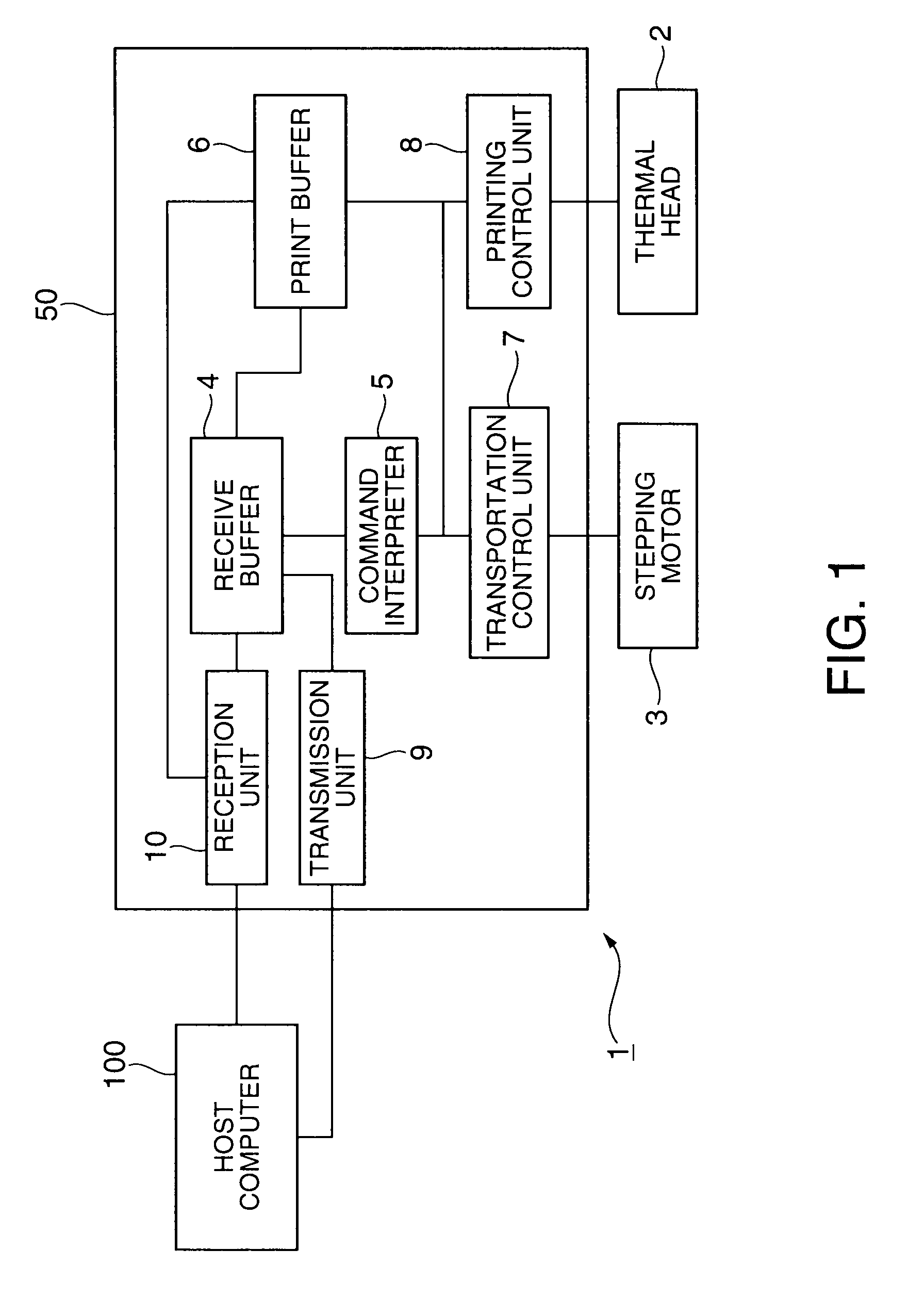
[0034]A preferred embodiment of an image processing device according to the present invention is described below with reference to the accompanying figures using a thermal printer by way of example. This embodiment of the invention uses by way of example a thermal printer that is communicably connected to a host computer for printing and is suitable for use in a POS system, for example.

[0035]FIG. 1 is a control block diagram showing the main control parts of a thermal printer 1 according to this embodiment of the invention. The thermal printer 1 has a thermal head 2, a stepping motor 3, and a printer control device 50 that controls driving the thermal head 2 and the stepping motor 3. The stepping motor 3 drives a platen roller that conveys the printing paper passed the printing position of the thermal head 2.

[0036]The printer control device 50 has a reception unit 10, a receive buffer 4, a command interpreter 5, a print buffer 6 (image conversion unit), a transportation control unit...


PUM


Abstract

A printer that writes print data to the print buffer and runs the paper feed and printing process while receiving image data from a host computer desirably balances the speed of the paper feed and printing process and the speed of the conversion process to enable continuous printing so that white stripes do not appear in the printout. A print process run command and conversion format information specifying the conversion format for converting color block data in a print buffer 6 are temporarily stored. Based on the conversion format information stored in the receive buffer 4, whether the color block data can be transferred directly to the print buffer 6 and converted is determined (step S12). If direct transfer to the print buffer 6 is possible, the color block data sent after the conversion format information is directly transferred to the print buffer 6 without storing to the receive buffer 4, and the printing process is run according to the print process run command (step S16).

Description

CROSS-REFERENCE TO RELATED APPLICATIONS[0001]Japanese Patent application No. 2007-047583 is hereby incorporated by reference in its entirety.BACKGROUND[0002]1. Field of Invention[0003]The present invention relates to a printer and to a printer control method for converting and writing graphic data that is sent from a host computer to a printer to the print buffer and executing the printing process while receiving the graphic data.[0004]2. Description of Related Art[0005]Printers that print both image data and character data generally always temporarily store print data received from a host computer to a receive buffer whether the received print data is image data or character data, and then sequentially read and convert the print data from the receive buffer to bitmap images, and write the bitmap images to the print buffer. This results in a time-consuming reception and conversion process when printing large image data files and thus lowers printing process speed.[0006]Addressing th...

Claims


Application Information

Patent Timeline
IPC IPC(8): G06F15/00
CPCG06K15/028G06K15/16G06K15/1801G06K15/186G06F3/1284G06F3/1211G06F3/1244G06F3/1267G06F3/1208G06F3/12
Inventor WAKASA, SHUNICHI
Owner SEIKO EPSON CORP
Learn More