Display apparatus

a technology of display device and display case, which is applied in the direction of casing/cabinet/drawer details, electric apparatus, instruments, etc., can solve the problems of front cover, deformation of design, and difficulty in forming thin plate display device into excellent cabinet form, and achieves convenient assembly, low cost, and excellent form.

Inactive Publication Date: 2008-08-28
SONY CORP
View PDF18 Cites 18 Cited by
  • Summary
  • Abstract
  • Description
  • Claims
  • Application Information

AI Technical Summary

Benefits of technology

[0010]In addition, in conducting assembly work to mount the display device on the cabinet, it is necessary to configure a cabinet in consideration of the assembly workability for allowing assembly at low costs. However, some scheme is necessary to readily assemble a display device configured only of a thin plate such as glass.
[0011]It is thus desirable to provide a display apparatus which can be readily assembled and has an excellent form that makes use of the reduction in the thickness of a display device.

Problems solved by technology

In the slim display apparatus like this, it is difficult to form a thin plate display device into an excellent cabinet form that makes use of the slim shape of the display device, as the configuration in which the display device is accommodated in the cabinet for accommodating the display device.
In other words, for example, screws are used to fix a front cover to the display device side, which causes a problem that the design is degraded.
In the case in which a form is considered that uses no screws to fix a front cover to the display device side, it is necessary to provide a relatively complex mechanism on the front cover side or on the display device side, and it can be assumed as well that the thickness of the front cover, for example, is increased because of the mechanism, which leads to a factor of hampering a reduction in the thickness of the display apparatus.
However, it is difficult to say that the cabinet structure of the display device before is a cabinet form that makes use of the slim form of the display device.
However, when the cabinet in the configuration before is applied as it is, it is difficult to reduce the thickness of the display apparatus that makes use of the slim form of the display device.

Method used


Image

  • Display apparatus
  • Display apparatus
  • Display apparatus

Examples


Embodiment Construction

[0026]Hereinafter, an example according to an embodiment of the invention will be described with reference to the accompanying drawings.

[0027]The example according to the embodiment is adapted to a display apparatus as a television set using a slim display device configured of an organic EL display (electroluminescent display). The organic EL display is a display device that is configured in which light emitting elements are arranged on a thin plate substrate in a matrix. For the display device in the example, such a display device is used that is configured in which light emitting elements are arranged on a glass substrate.

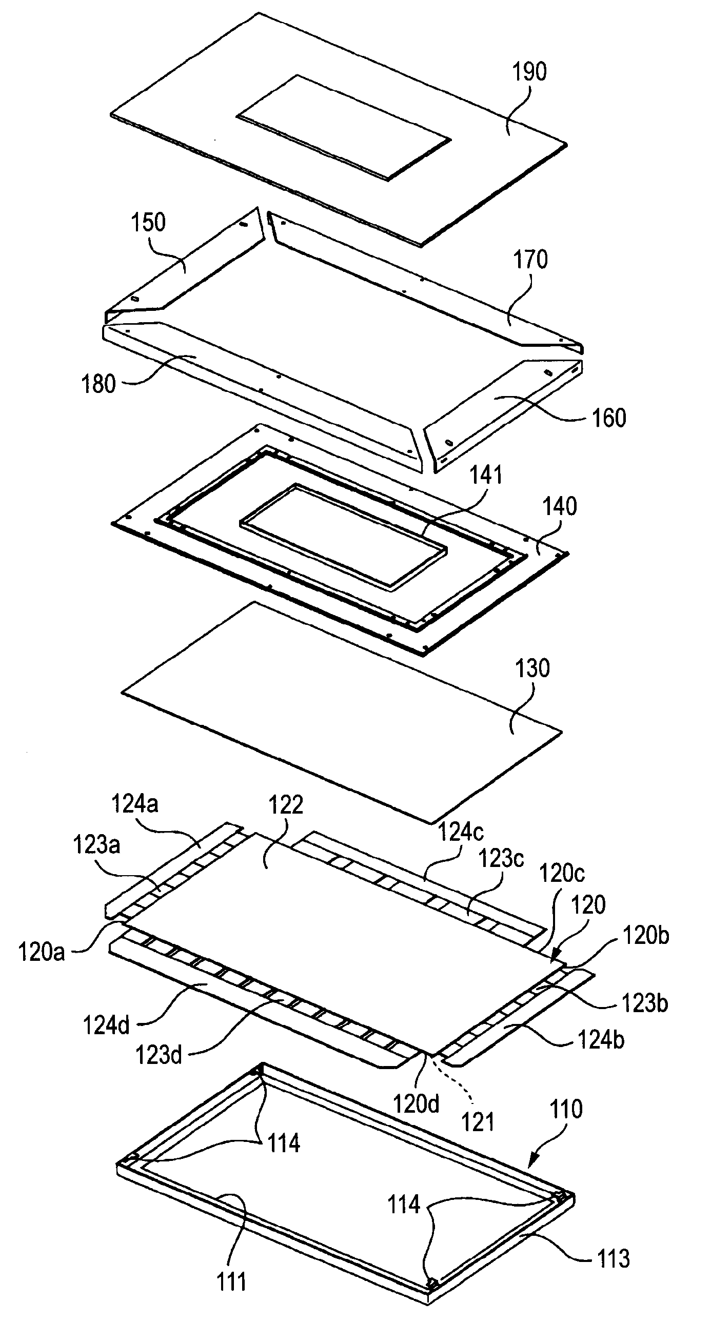
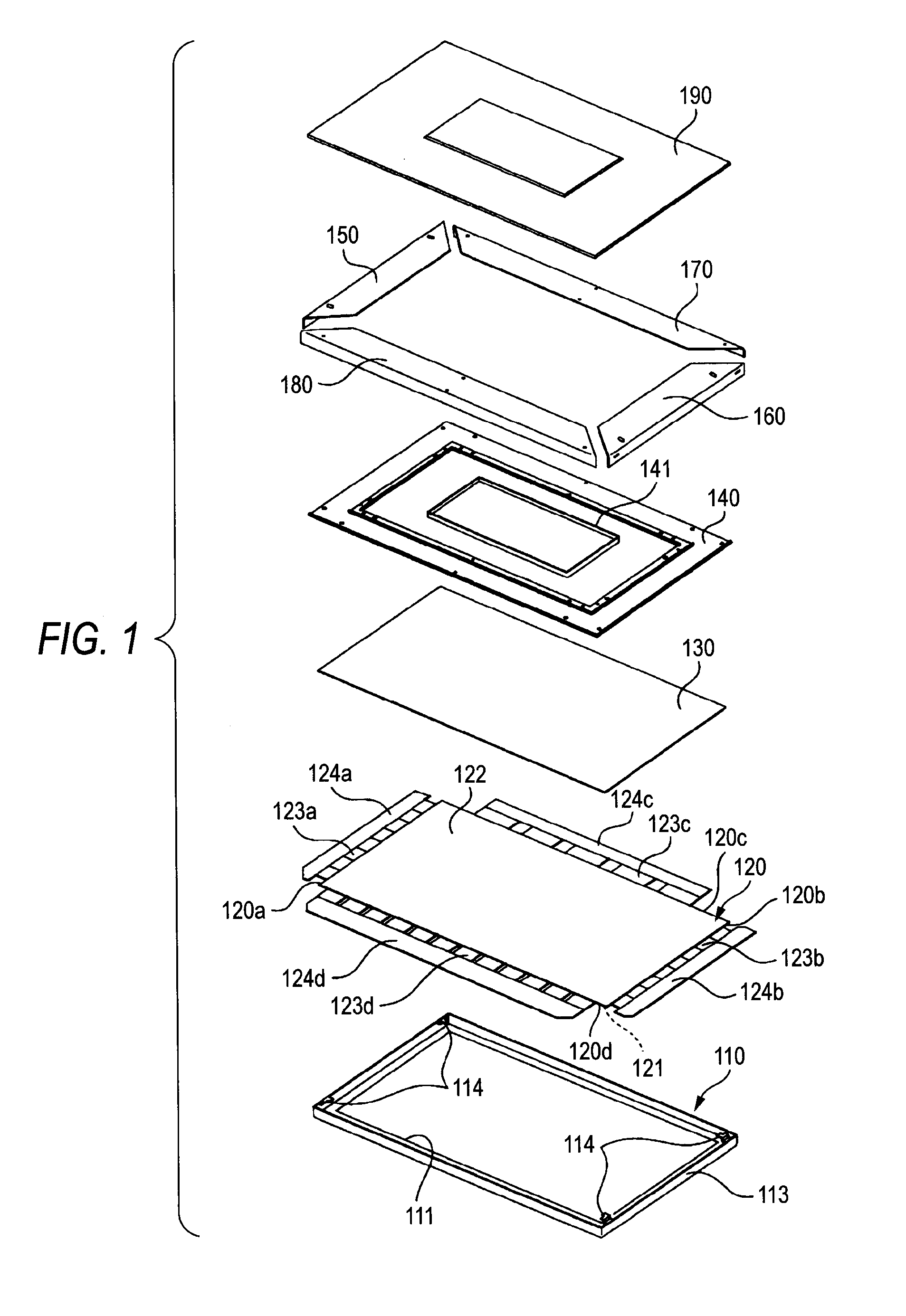
[0028]For example, as shown in FIG. 9, a display apparatus 100 according to the example of the embodiment is in the state in which a front surface 121 of a display device is exposed from a window part 111 of a front cover 110 and the exposed front surface 121 is an image display surface.

[0029]FIG. 1 shows an exploded diagram depicting the display apparatus 100 ac...


PUM


Abstract

A display apparatus includes: a thin plate display device having an image display surface and a back surface; a front cover that covers an outer area and end surfaces of the display surface of the display device; and a back surface cover mounted so as to cover the back surface, the cover being divided into a plurality of parts, wherein a projecting or recessed part is provided at a plurality of places on the front cover facing the end surfaces, a recessed or projecting part is provided that is fit into the projecting or recessed part facing thereto, on the back surface cover, and a slide mechanism part is provided in which the back surface cover is formed to move in parallel along the back surface of the display device and the fitting is achieved by the parallel motion.

Description

CROSS REFERENCES TO RELATED APPLICATIONS[0001]The present invention contains subject matter related to Japanese Patent Application JP 2007-050251 filed in the Japanese Patent Office on Feb. 28, 2007, the entire contents of which being incorporated herein by reference.BACKGROUND OF THE INVENTION[0002]1. Field of the Invention[0003]The present invention relates to a display apparatus using a slim display device such as an organic electroluminescent (EL) display, particularly to the configuration of a cabinet assembled as a display apparatus.[0004]2. Description of the Related Art[0005]As a display apparatus having a thin plate display device such as an organic EL display, a plasma display or a liquid crystal display, there is a display apparatus having a front cover that covers the display surface of a display device and a rear cover that covers the opposite side of the display surface (see JP-A-H05-103284 (Patent Reference 1)).[0006]In the display apparatus like this, for example, a ...

Claims


Application Information

Patent Timeline
Patent Type & Authority Applications(United States)
IPC IPC(8): H05K7/00
CPCH05K5/02
Inventor SAKATA, TATSUYA
Owner SONY CORP
Why Eureka
Try Eureka