
Estimating delay of an echo path in a communication system

a communication system and delay estimation technology, applied in the field of communication systems and equipment, can solve problems such as signal processing and transmission delay, affecting the transmission of voiceband data, fax and text, and users' difficulty in talking or listening over a telephone connection

Inactive Publication Date: 2008-08-28
NXP USA INC
View PDF10 Cites 37 Cited by
  • Summary
  • Abstract
  • Description
  • Claims
  • Application Information

AI Technical Summary

Problems solved by technology

The objectionable effect of echo results from a combination of reflections from network components such as two- to four-wire converters (e.g., an impedance mismatch of a hybrid circuit, which is a device used to convert signals from a four-wire communication network interface to a two-wire local subscriber loop, and vice versa), together with signal processing and transmission delay.
Echo may cause users difficulty in talking or listening over a telephone connection, and it may also affect the transmission of voiceband data, fax and text.
The adaptive signal processing circuits unfortunately may increase the complexity and computational costs associated with rapid and accurate echo signal identification and cancellation or removal.

Method used


Image

  • Estimating delay of an echo path in a communication system
  • Estimating delay of an echo path in a communication system
  • Estimating delay of an echo path in a communication system

Examples


Embodiment Construction

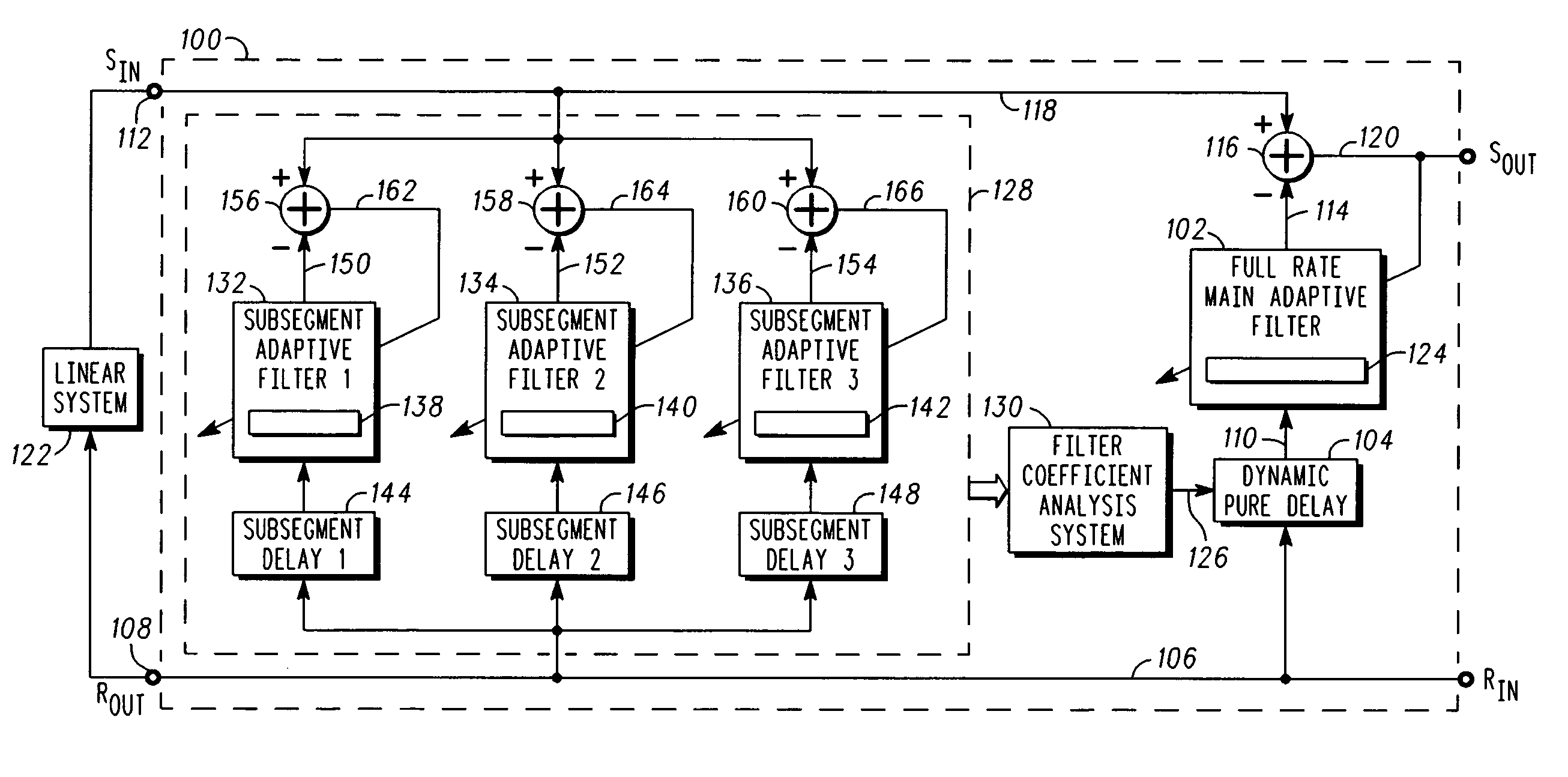
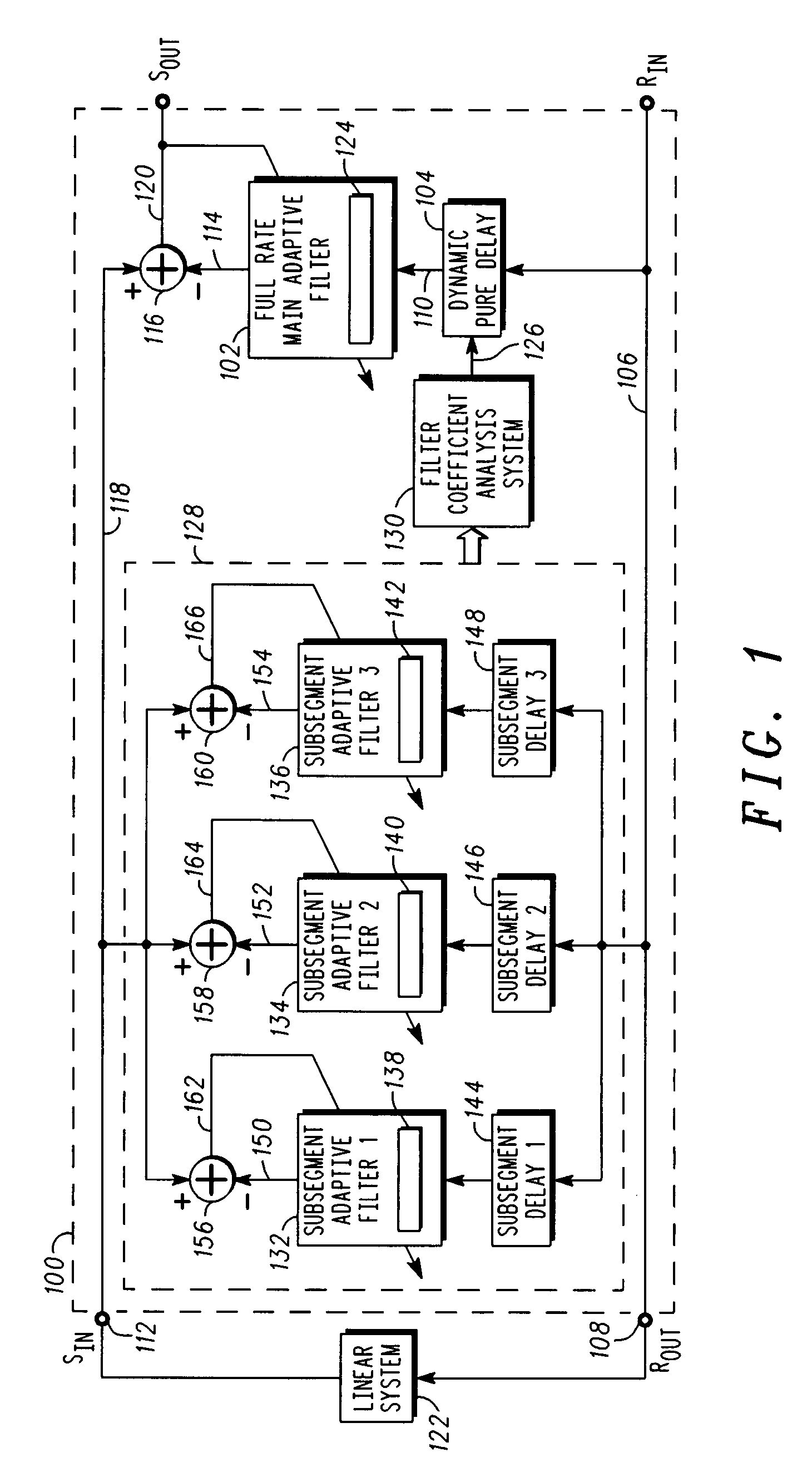
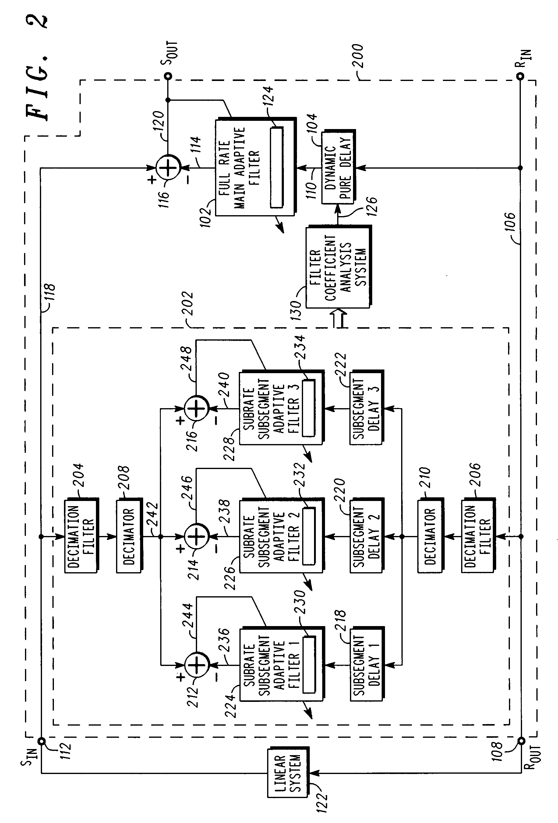
[0014]Referring to FIG. 1, a high-level block diagram of portions of a system for reducing echo signals in accordance with one or more embodiments will be briefly discussed and described. Note that many of the processes and functional blocks described hereinafter operate in the digital domain using digital data representing speech or other data transmitted over a communication network. As shown (note that not all major elements / subsystems of an echo canceller system are depicted in FIG. 1), echo reduction system 100, which can also be referred to as an echo canceller, includes full rate main adaptive filter 102 coupled to dynamic pure delay 104. Dynamic pure delay 104 has an input coupled to receive signal 106 (which is represented schematically at signal path 106, as are other “signals” similarly referred to herein with reference to FIGS. 1, 2, and 3), which also may be known as the “Rin” signal, as used in ITU-T Recommendation G.168, and other similar documents. An output of dynam...


PUM


Abstract

Methods and corresponding systems for reducing an echo signal include assigning a subsegment delay to each of a plurality of subsegment adaptive filters. A send signal and a delayed receive signal are coupled to each of the subsegment adaptive filters, wherein the delayed receive signal is delayed according to a respective subsegment delay. A set of filter coefficients in each of the subsegment adaptive filters are adapted, in parallel, to correspond to a respective subsegment impulse response of a connected system. Each set of filter coefficients is analyzed to produce a pure delay, and the pure delay is used to delay the receive signal for a main adaptive filter. An echo signal replica is produced using the main adaptive filter and an error signal. The echo signal replica is subtracted from the send signal to produce the error signal.

Description

BACKGROUND[0001]1. Field[0002]This disclosure relates generally to communication systems and equipment, and more specifically, to techniques and apparatus for echo cancellation or echo reduction in a communication system.[0003]2. Related Art[0004]Echo has a major effect on voice quality in telecommunication networks (such as the Public Switching Telephone Network (PSTN) or Packet Telephony (PT) network). The objectionable effect of echo results from a combination of reflections from network components such as two- to four-wire converters (e.g., an impedance mismatch of a hybrid circuit, which is a device used to convert signals from a four-wire communication network interface to a two-wire local subscriber loop, and vice versa), together with signal processing and transmission delay. Echo may cause users difficulty in talking or listening over a telephone connection, and it may also affect the transmission of voiceband data, fax and text.[0005]Echo cancellation is used in a telecomm...

Claims


Application Information

Patent Timeline
IPC IPC(8): H04M9/08
CPCH04M3/002H04B3/237
Inventor DYBA, ROMAN A.HE, PERRY P.
Owner NXP USA INC
Learn More