
Fiber optic splice trays

a fiber optic splice and splice technology, applied in the direction of mountings, optical elements, instruments, etc., can solve the problems of optical fiber performance degradation and/or failure, and achieve the effects of improving functionality, improving slack storage, and small areas

Inactive Publication Date: 2008-08-28
CORNING OPTICAL COMM LLC
View PDF99 Cites 99 Cited by
  • Summary
  • Abstract
  • Description
  • Claims
  • Application Information

AI Technical Summary

Benefits of technology

The present invention provides better performing splicing tools with more efficient space usage for storing excess material. These improvements are achieved through design changes made on existing splave plates which create smaller spaces within them while still maintaining their function.

Problems solved by technology

The technical problem addressed in this patent text relates to reducing the size and cost of splice trays and their associated splave assemblies in fiber optic data and communication networks. Additionally, it seeks to improve the ease of installation and accessibility of these components in different settings and orientations.

Method used


Image

  • Fiber optic splice trays
  • Fiber optic splice trays
  • Fiber optic splice trays

Examples


Embodiment Construction

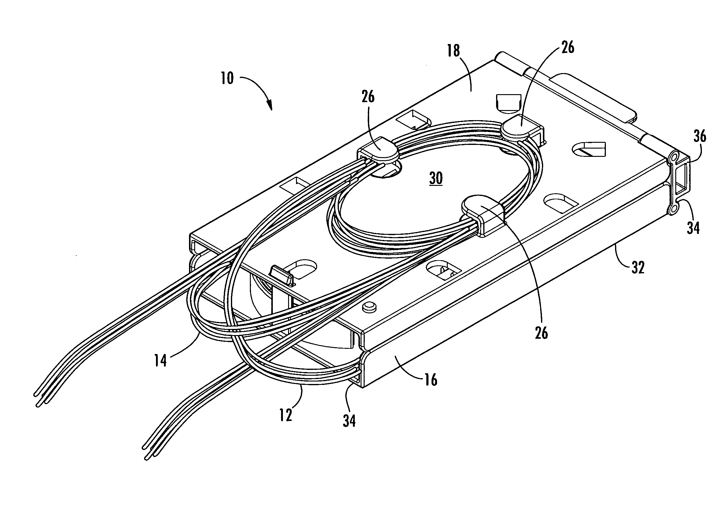
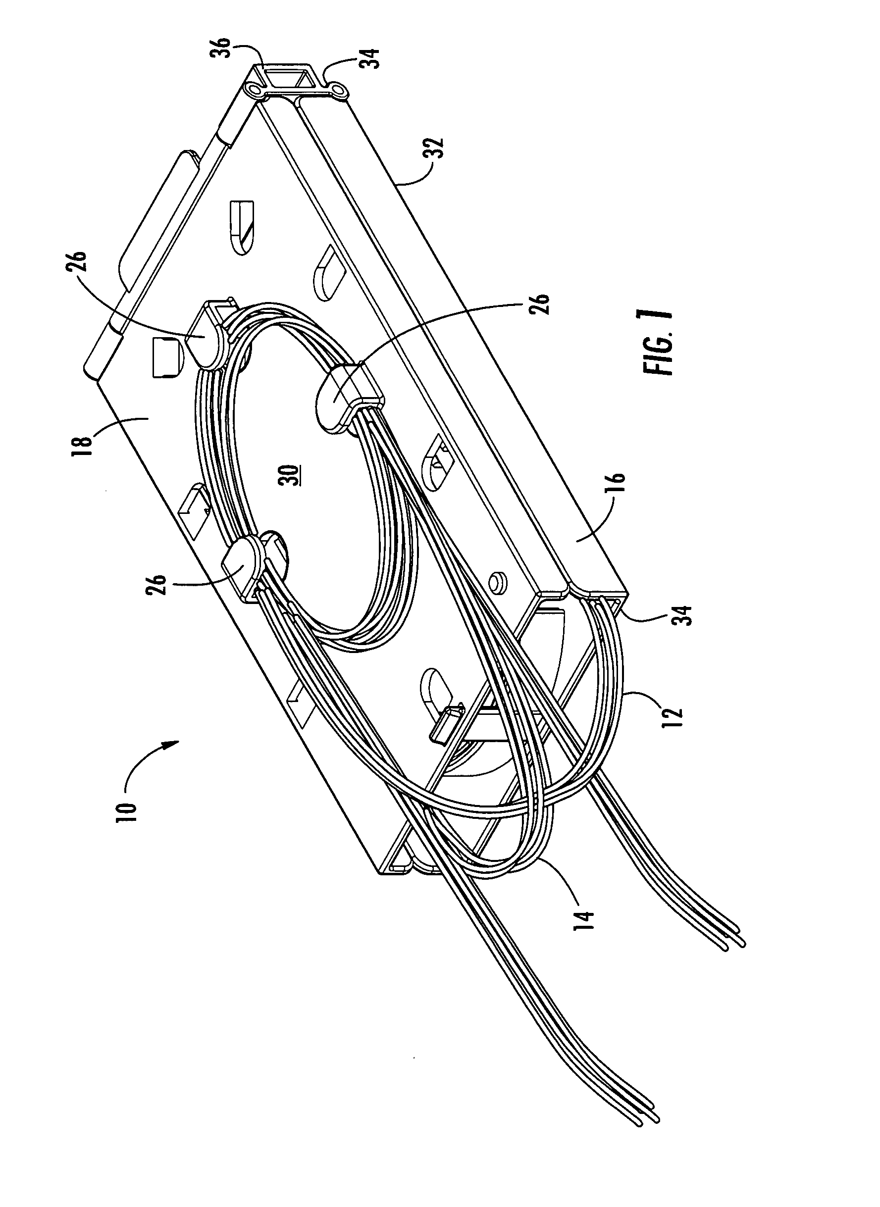
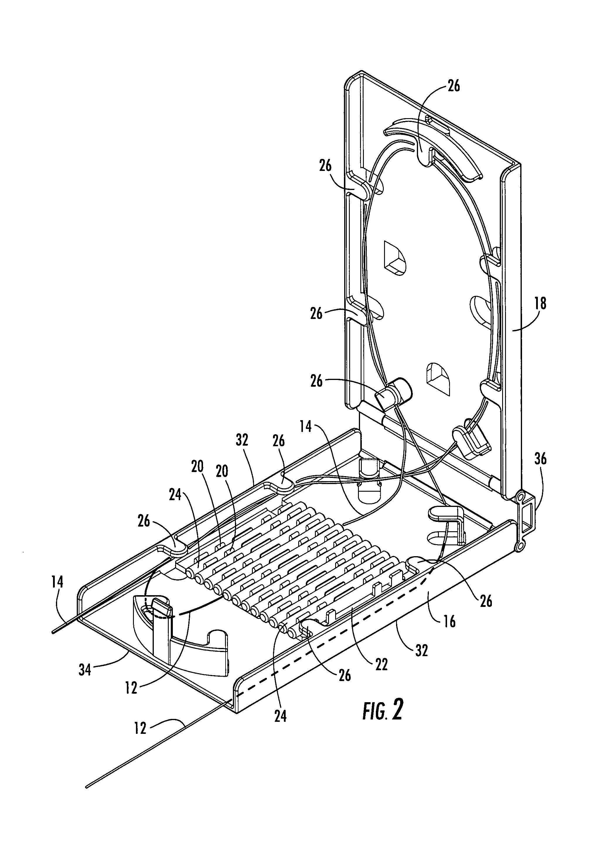
[0028]The present invention now will be described more fully hereinafter with reference to the accompanying drawings, in which some, but not all embodiments of the invention are shown. Indeed, the invention may be embodied in many different forms and should not be construed as limited to the embodiments set forth herein; rather, these embodiments are provided so that this disclosure will satisfy applicable legal requirements. Although apparatus and methods for providing splices of microstructured optical fibers are described and shown in the accompanying drawings with regard to specific types of splice trays and splice assemblies, it is envisioned that the functionality of the various apparatus and methods may be applied to any now known or hereafter devised splice trays and splice assemblies in which it is desired to provide splices of optical fibers. Like numbers refer to like elements throughout.

[0029]With reference to FIGS. 1-16, a splice tray and a splice assembly in accordance...


PUM


Abstract

There is provided splice trays and splice assemblies that provide convenient access to optical fiber slack within a relatively small area or volume. Some splice trays are adapted for use with microstructured optical fibers to further reduce the size of the splice tray or splice assembly. Some splice trays provide fiber routing devices on the cover of the splice tray. The fiber routing device may be positioned on an inside surface of the cover and/or on an outside surface of the cover. The splice trays and/or splice assemblies may be used with or as fiber drop terminals used within multiple dwelling units.

Description


Claims


Application Information

Patent Timeline
Owner CORNING OPTICAL COMM LLC
Learn More