High Pressure Pump Control

a high-pressure pump and feedback controller technology, which is applied in fluid pressure control, positive displacement liquid engines, instruments, etc., can solve the problems of increasing the pressure of the compressed solvent, increasing the thermal effect at high pressure, so as to reduce the error of solvent delivery, and eliminate the effect of delivery error

Active Publication Date: 2008-08-28
WATERS TECH CORP
View PDF39 Cites 47 Cited by
  • Summary
  • Abstract
  • Description
  • Claims
  • Application Information

AI Technical Summary

Benefits of technology

[0012]It is an object of the present invention to prevent solvent composition errors when the flow from two pumps is used to create a solvent gradient by correcting the delivered flow deficit occurring after solvent compression.
[0037]controlling an output of a high pressure solvent pump system to reduce delivery error, wherein the high pressure pump system includes a primary piston and an accumulator piston, each piston having a velocity and pressure associated therewith; and

Problems solved by technology

In fact, improvements in one technological area or subsystem typically spurn on advancement in interrelated areas or subsystems.
For many leading edge technology HPLC instruments, the high pressure and limited amount of time to compress the solvent creates significant thermal effect.
However, the thermal effects at high pressure become more appreciable.
The thermal effects create errors in the pressure of the compressed solvent because the solvent temperature is elevated during compression compared with during analysis in the instrument.
As a result, the compressed solvent settles to a pressure below the target pressure and, thereby, creates a deficit in delivered flow.
Prior art pump control systems lack the required ability to react to the thermal effects of solvent compression at high pressures.
So despite the advances of the state of the art, HPLC instruments are lacking in stability and performance.
As a result, inaccurate results are still common.
Moreover, such prior art instruments are plagued by inadequacies such as complex electronics and numerous additional components that undesirably increase costs and complexity without overcoming the noted drawbacks.

Method used


Image

  • High Pressure Pump Control
  • High Pressure Pump Control
  • High Pressure Pump Control

Examples


Embodiment Construction

[0050]The present invention overcomes many of the prior art problems associated with controlling high pressure pumps. The advantages, and other features of the system disclosed herein, will become more readily apparent to those having ordinary skill in the art from the following detailed description of certain preferred embodiments taken in conjunction with the drawings which set forth representative embodiments of the present invention.

Solvent Delivery System Background

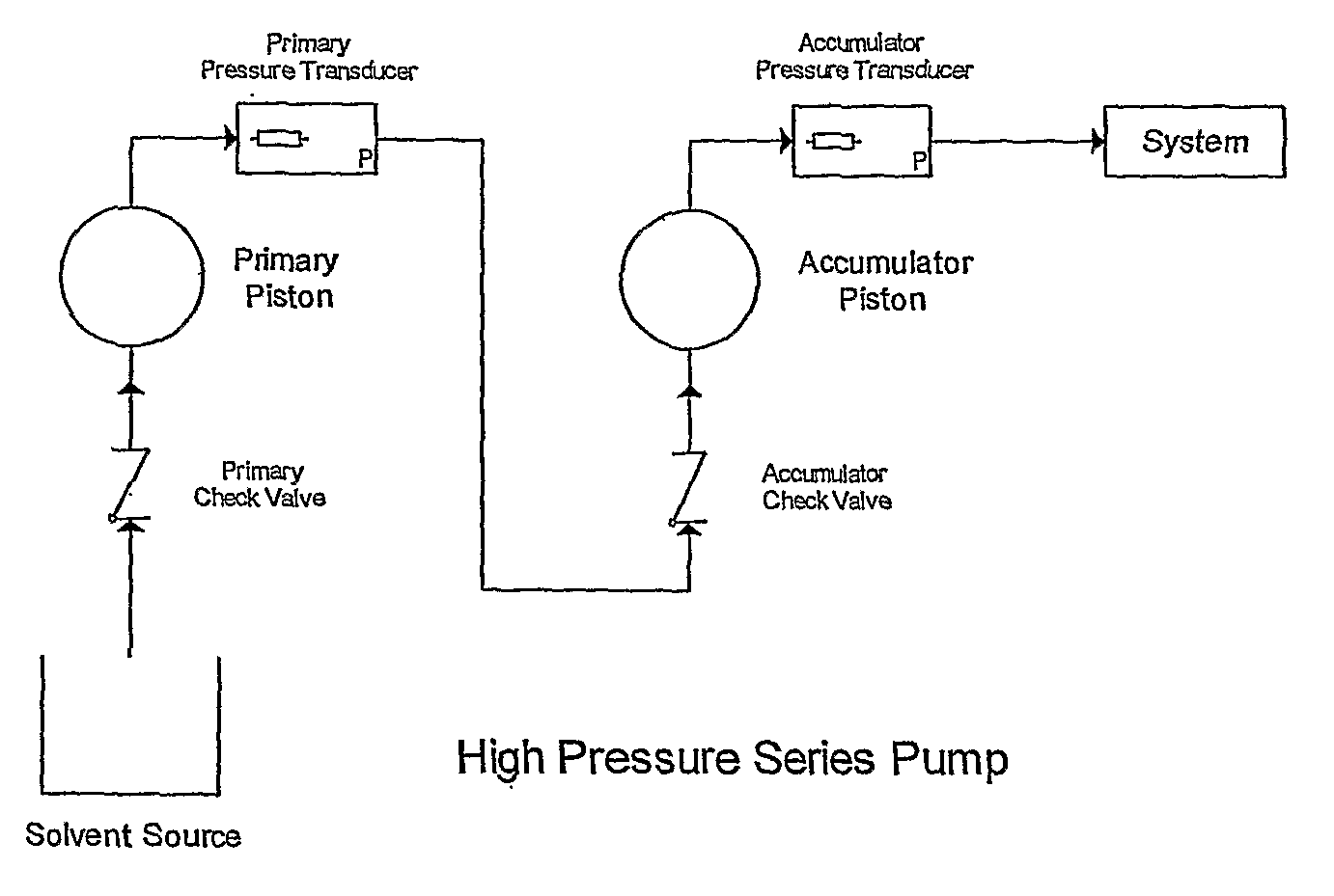
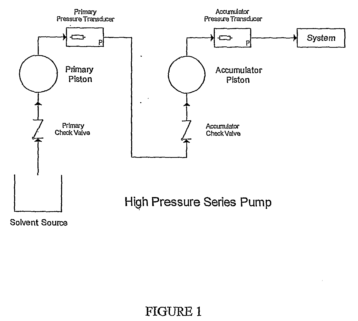
[0051]Referring to FIG. 1, a schematic view of a high pressure serial pump is illustrated. High pressure pumps for use in chromatography applications normally use a reciprocating type of design involving two pistons. Depending on the fluidic configuration, there are two main design types: parallel or series. In the parallel design, the two pistons alternate in operation whereby one piston delivers flow while the other intakes new solvent from the solvent source. In the series design, only one piston intakes solvent f...


PUM


Abstract

A feedback control loop for a high pressure pump modifies the accumulator velocity and pressure during solvent transfer. The accumulator velocity is adjusted to maintain the system pressure equal to the expected pressure to thereby eliminate the effect of the flow deficit created by a thermal effect.

Description

RELATED APPLICATIONS [0001]This application claims the benefit of U.S. Provisional Application No. 60 / 587,381 filed Jul. 13, 2004, the entire contents of which are incorporated herein by reference.BACKGROUND OF THE INVENTION [0002]1. Field of the Invention[0003]The subject invention is directed generally to a scientific laboratory analytical equipment, and more particularly, to analytic equipment with a closed loop feedback controller for a high pressure pump.[0004]2. Background of the Related Art[0005]Scientific laboratories commonly need to separate chemical compounds on such basis as the compounds molecular weight or size, charge or solubility. Separation of the compounds is often a first step in the identification, purification and quantification of the compounds. Chromatography or, more specifically, high performance liquid chromatography (BPLC) has become the analytical tool of choice for applications as varied as biotechnological, biomedical, and biochemical research as well ...

Claims


Application Information

Patent Timeline
Patent Type & Authority Applications(United States)
IPC IPC(8): F04B49/06F04B49/20F04B49/00G05D7/00G05D16/00
CPCF04B11/0058F04B11/0075F04B23/06F04B49/065G01N2030/326F04B2205/05F04B2205/09F04B2205/10F04B2205/11F04B2205/01G05D16/2066F04B49/06
Inventor DE CORRAL, JOSEPENSAK JR., STANLEY P.
Owner WATERS TECH CORP
Why Eureka
Try Eureka