

Image forming apparatus and image forming method
- Summary
- Abstract
- Description
- Claims
- Application Information
AI Technical Summary
Benefits of technology
Problems solved by technology
Method used
Image

Examples
first embodiment
Modification of First Embodiment
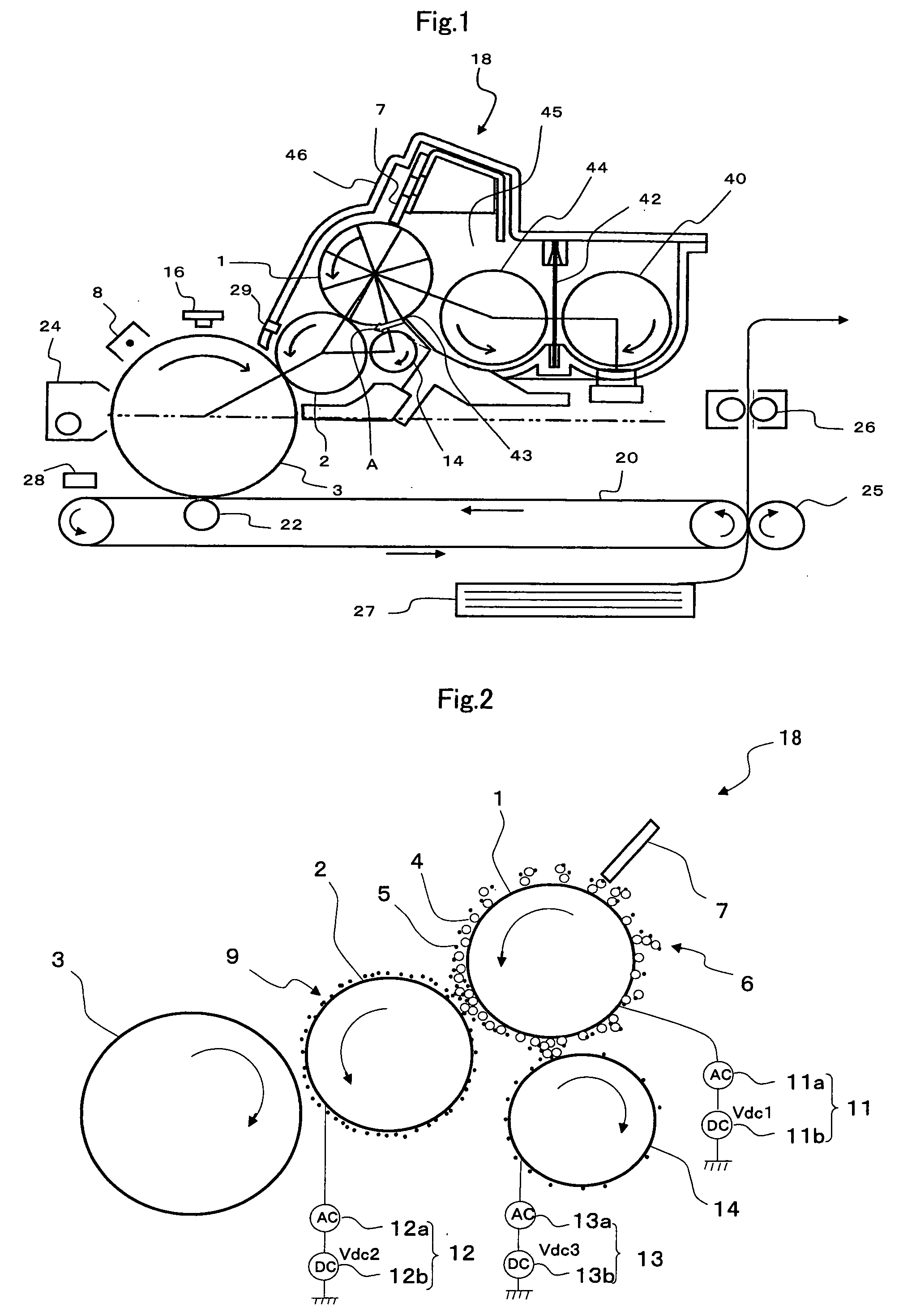
[0103]The control of the bias voltage applied to the toner collecting roller 14 by the bias means 13 may be control in accordance with the toner charge amount on the developing roller 2 in place of the control in accordance with ΔV in the first embodiment. However, here, in the control, the toner charge amount on the developing roller 2 is a toner charge amount on the developing roller 2 calculated from a surface potential of the developing roller 2 and a toner density of an image patch. Therefore, in the present embodiment, surface potential sensing means 29 for sensing the surface potential of the developing roller 2 is provided, and as the surface potential sensing means 29, a surface potential sensing sensor is used. FIG. 5 shows one example of the control of the bias voltage applied to the collecting roller 14 in the present embodiment in a flowchart.
[0104]As shown in FIG. 5, during the image formation, if the development driving time exceeds pre...
second embodiment
[0108]Hereinafter, a second embodiment of the present invention will be described in detail based on the drawings. FIG. 7 is an explanatory diagram showing a schematic configuration of a touchdown developing type image forming apparatus according to this embodiment. FIG. 8 is a schematic configuration diagram showing part of developing means in FIG. 7. For the same members as those in the first embodiment, the same reference numerals are given, and their description may be omitted.
(Image Forming Apparatus)
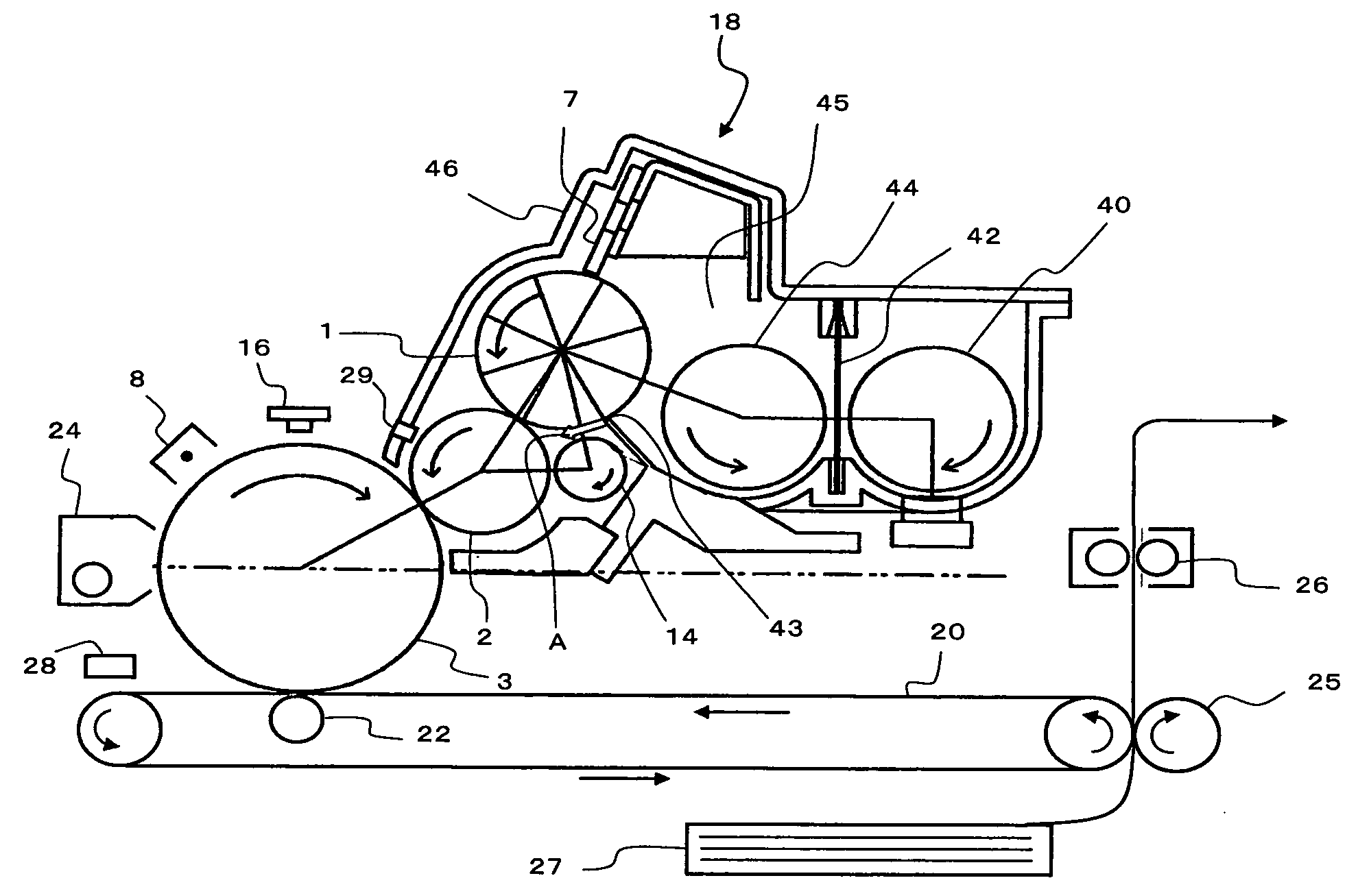
[0109]The image forming apparatus of this embodiment forms an image by a so-called touchdown developing method as described before. As shown in FIG. 7, the image forming apparatus is provided with the photoreceptor 3 (electrostatic latent image holding body), and around this photoreceptor 3, the charging means 8, the exposing means 16, the developing means 18, the primary transfer means 22, the secondary transfer means 25, the fixing means 26, the cleaning means 24 and the like are...
third embodiment
[0137]Hereinafter, an embodiment of the present invention will be described in detail based on the drawings. FIG. 11 is an explanatory diagram showing a schematic configuration of a touchdown developing type image forming apparatus according to one embodiment of the present invention. FIG. 12 is a schematic configuration diagram showing part of developing means in FIG. 1. For the same members as those in the first and second embodiments, the same reference numerals are given, and their description may be omitted.
(Image Forming Apparatus)
[0138]The image forming apparatus of this embodiment forms an image by a so-called touchdown developing method as described before. As shown in FIG. 11, the image forming apparatus is provided with the photoreceptor 3 (electrostatic latent image holding body), and around this photoreceptor 3, the charging means 8, the exposing means 16, the developing means 18, the primary transfer means 22, the secondary transfer means 25, the fixing means 26, the c...
PUM
 Abstract
Description
Claims
Application Information