Moving image processing apparatus, control method thereof, and program

Inactive Publication Date: 2009-10-15
CANON KK
View PDF4 Cites 2 Cited by
  • Summary
  • Abstract
  • Description
  • Claims
  • Application Information

AI Technical Summary

Benefits of technology

[0017]The present invention has been made to solve the above-described problems, and the present invention provides to provide a moving image processing apparatus capable of preventing generation of a

Problems solved by technology

In this method, however, the next frame image A2/B1 is generated from field images of different times and is therefore visually unnatu

Method used


Image

  • Moving image processing apparatus, control method thereof, and program
  • Moving image processing apparatus, control method thereof, and program
  • Moving image processing apparatus, control method thereof, and program

Examples


Example

First Embodiment

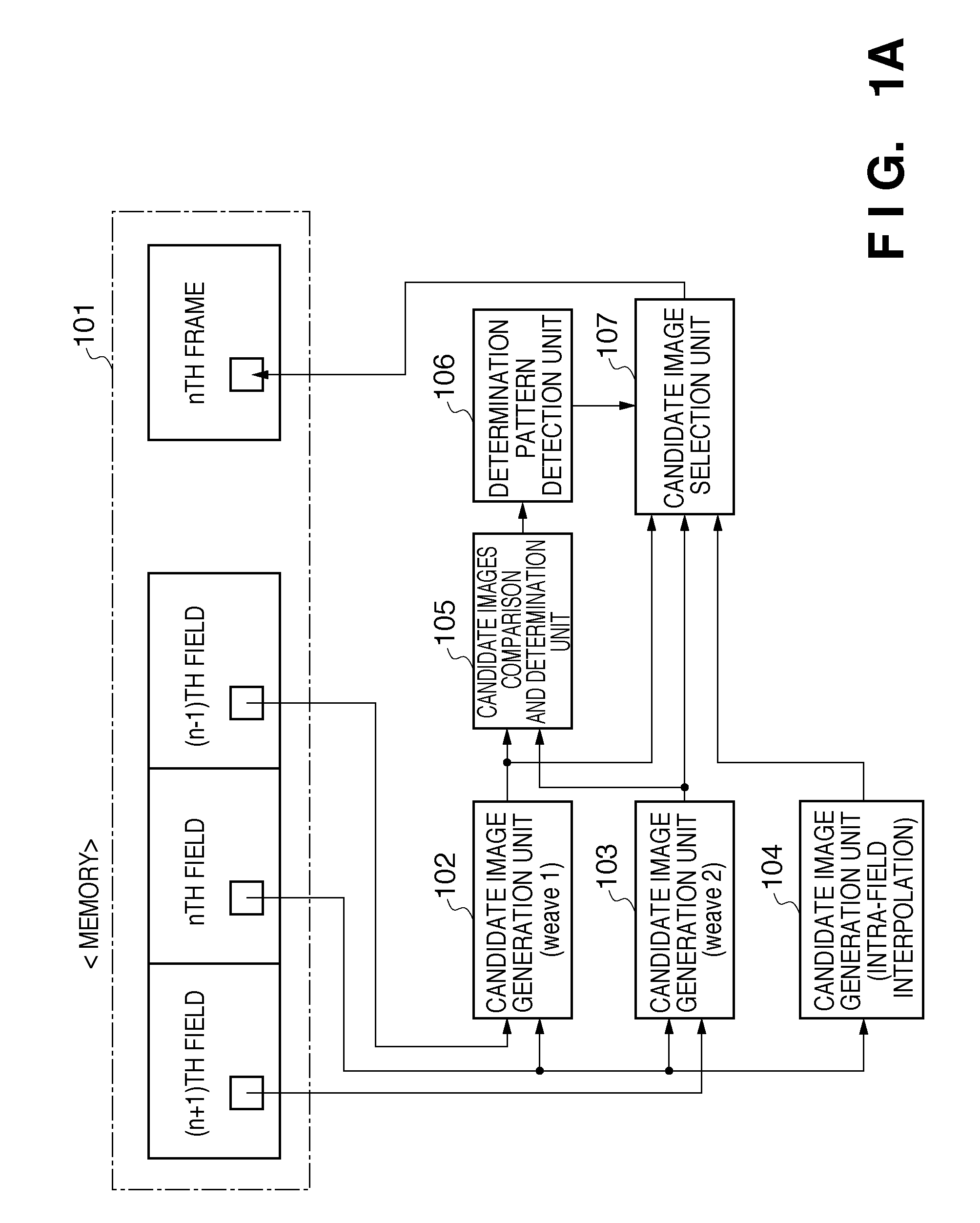
[0042]FIG. 1A is a block diagram showing the functional arrangement of a moving image processing apparatus according to the first embodiment of the present invention.

[0043]The moving image processing apparatus of the first embodiment reads out three field images simultaneously from a memory 101, processes these inputs, generates one frame image as an output, and writes it in the memory 101.

[0044]The three field images are an nth current field image, a (n−1)th field image chronologically immediately before the nth current field image, and a (n+1)th field image chronologically immediately after the nth current field image.

[0045]A first candidate image generation unit 102 combines the current field image with the immediately preceding field image as data of the same time, thereby generating a frame image (first candidate image). A second candidate image generation unit 103 combines the current field image with the immediately succeeding field image as data of the same t...

Example

Second Embodiment

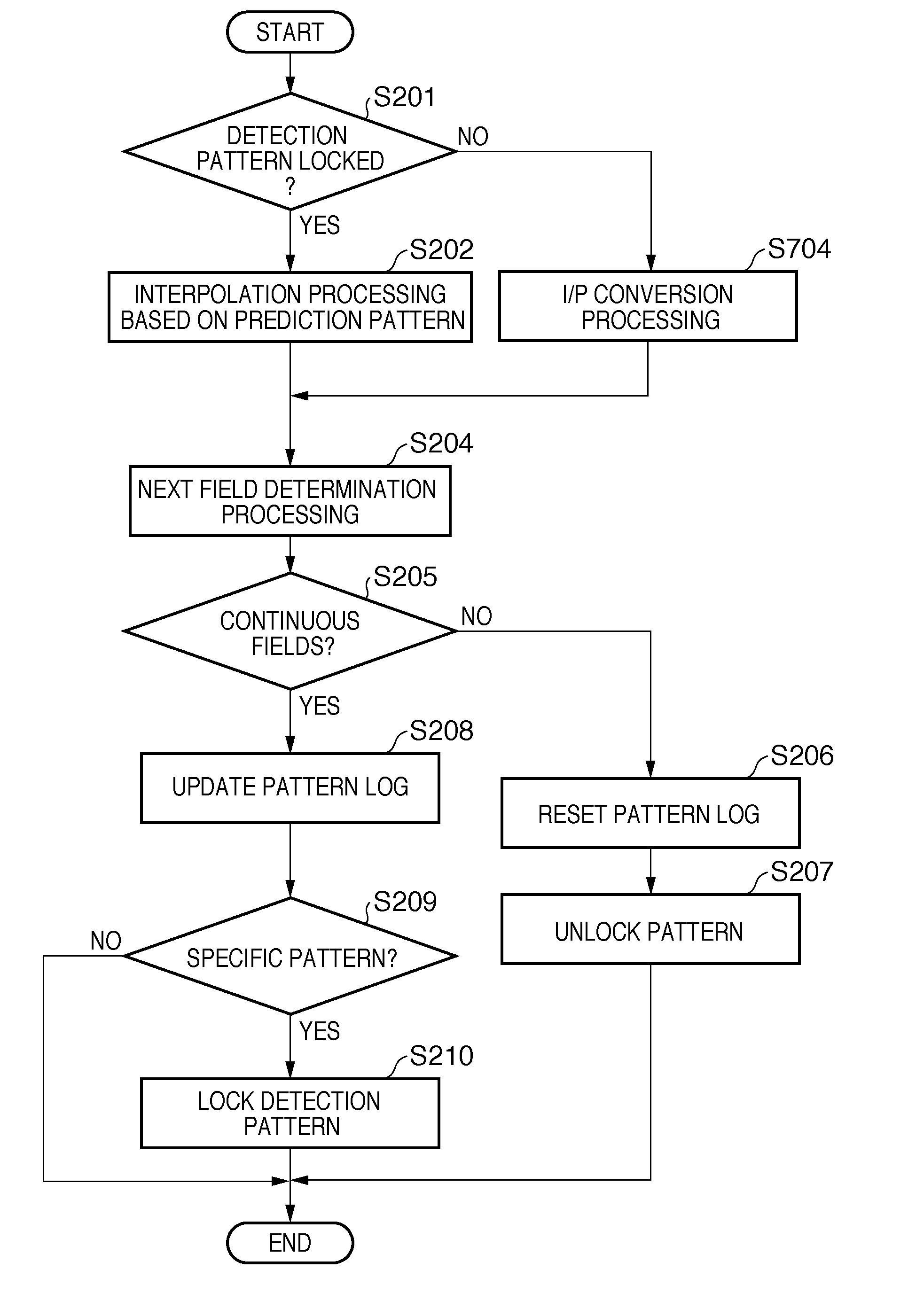
[0120]A moving image processing apparatus according to the second embodiment includes a motion adaptive I / P conversion processing unit 604 in place of the third candidate image generation unit 104 in FIG. 1A of the first embodiment, as shown in FIG. 6. I / P conversion is to convert a field image that is an interlaced image (I mage) into a frame image that is a progressive image (P image). Especially, the motion adaptive I / P conversion processing unit 604 generates one frame from two field images, i.e., a current field image and a preceding field image.

[0121]Detailed processing of the moving image processing apparatus according to the second embodiment will be described next with reference to FIG. 7.

[0122]FIG. 7 is a flowchart illustrating processing to be executed by the moving image processing apparatus according to the second embodiment of the present invention.

[0123]Unlike the flowchart in FIG. 2 of the first embodiment, if the detection pattern is not locked, the...


PUM


Abstract

A frame image is generated by combining a current field image and a preceding field image as a first candidate image. A frame image is generated by combining the current field image and a succeeding field image as a second candidate image. A frame image is generated by pixel interpolation processing for the current field image and output as a third candidate image. It is determined whether the current field image has continuity to the preceding or succeeding field image, or no continuity with any of them. Based on the determination result, the determination result of the current field image is stored as log information. A specific pattern is detected from the pattern of stored log information of continuous field images before the current field image. One of the first to third candidate images is selected as the frame image of the current field image based on the detection result.

Description

BACKGROUND OF THE INVENTION[0001]1. Field of the Invention[0002]The present invention relates to a moving image processing apparatus for generating a frame image from a field image in a moving image, a control method thereof, and a program.[0003]2. Description of the Related Art[0004]To transmit and store moving image data, conventionally, an interlaced image (field image) with 60 fields per second is widely used. For transmission of digital broadcasting or digital data storage of DVDs, an interlaced image is compressed using moving image encoding based on MPEG-2. Even shooting by a video camera is generally done using an interlaced image with 60 fields per second.[0005]On the other hand, movie shooting and screening commonly use an image of 24 frames per sec. Hence, recording on a DVD is done normally by converting a progressive image (frame image) having 24 frames per sec into an interlaced image (field image) having 60 fields per sec.[0006]This conversion is called 2-3 pull-down ...

Claims


Application Information

Patent Timeline
IPC IPC(8): H04N7/01
CPCH04N5/144H04N7/0147H04N7/0137H04N7/012
Inventor ITOKAWA, OSAMU
Owner CANON KK
Why Eureka
Try Eureka