Cable clamping device and method of its use

a clamping device and cable technology, applied in the field of cable clamping devices and methods of their use, can solve the problems of soft tissue damage, stripping, devascularization at the site of fracture, etc., and achieve the effects of convenient percutaneous or near-percutaneous application, simplified tensioning and completion, and reduced risk

Inactive Publication Date: 2008-08-28
KRAEMER PAUL EDWARD
View PDF11 Cites 15 Cited by
  • Summary
  • Abstract
  • Description
  • Claims
  • Application Information

AI Technical Summary

Benefits of technology

[0017]An advantage of the present invention is that it facilitates percutaneous or near percutaneous application of surgical wires or cables in orthopedic fracture surgery.
[0018]Another advantage of the present invention is that it minimizes the risk of damaging soft tissue structures, stripping, and devascularization at the site of the fracture.

Problems solved by technology

Current devices and methods for the application of cables or wires around bone often res

Method used


Image

  • Cable clamping device and method of its use
  • Cable clamping device and method of its use
  • Cable clamping device and method of its use

Examples


Embodiment Construction

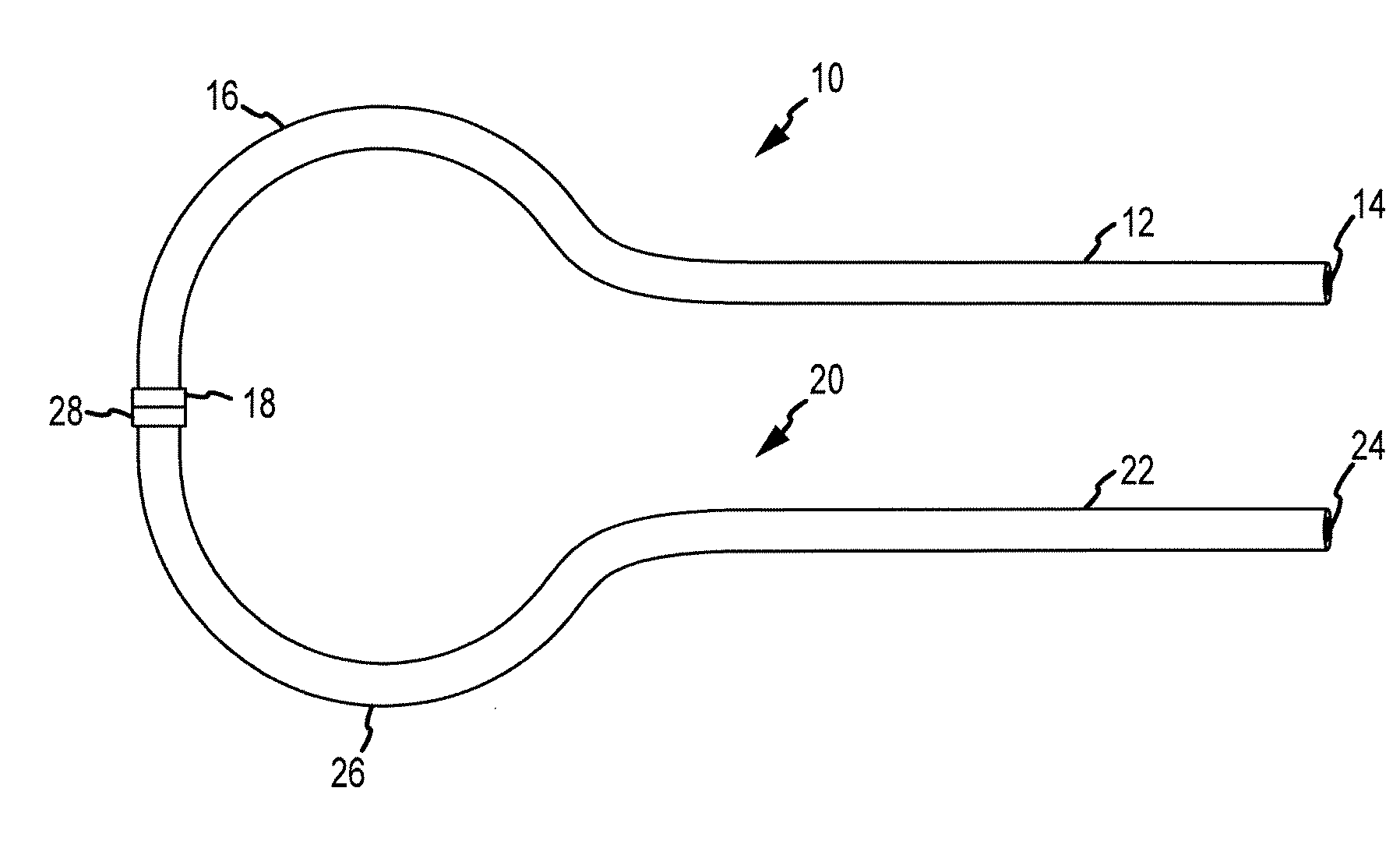
[0037]The present invention provides devices and methods for passing wires or cables around a structure that is concealed or otherwise difficult to access. The present invention will be described in connection with the application of surgical wires or cables around bone in percutaneous or near percutaneous orthopedic fracture surgery. A person of skill in the art will appreciate, however, that the invention may be applied in other contexts where it is desirable to wrap a cable, wire or other elongated line, such as a rope or string, around a concealed or obstructed structure.

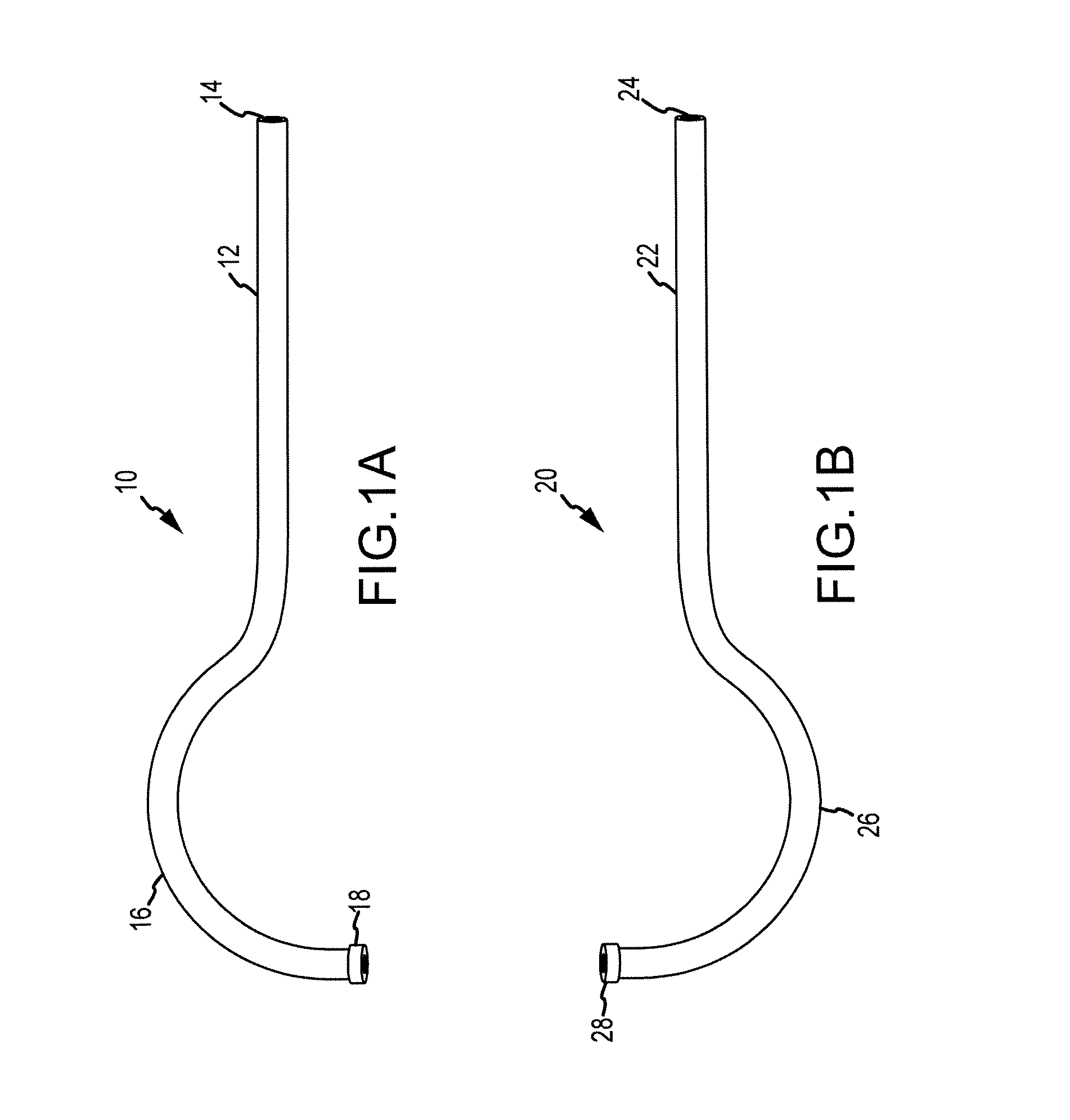
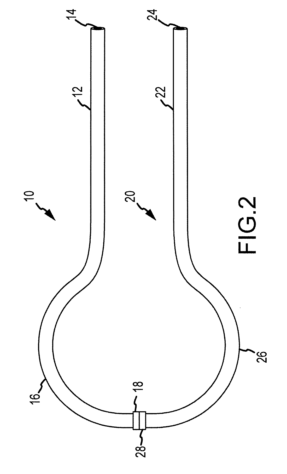
[0038]With reference to FIGS. 1A and 1B, a system according to one embodiment of the present invention is shown. FIGS. 1A illustrates a first flexible member 10 and FIG. 1B depicts a second flexible member 20. Each of first and second flexible members 10, 20 includes an outer wall 12, 22 defining a passageway 14, 24 extending through the flexible member and a curved distal portion 16, 26 having a distal tip 18, ...


PUM


Abstract

A cable clamp includes a housing having two substantially parallel and co-planar channels therethrough. At least one restraining member is disposed within the housing between the two channels, also substantially parallel and co-planar therewith. A surgical cable is passed through the first channel, around a bone or other structure, and through the second channel. The restraining member may then be actuated to impinge against the surgical wire or cable, simultaneously constraining the surgical wire or cable within both channels between the restraining member (an inner wall) and the housing (an outer wall). For example, the restraining member may be an expansion member that, when expanded as by driving a wedge between two restraining arms, reduces the size of the channels such that the surgical wire or cable can no longer pass freely therethrough.

Description

CROSS-REFERENCE TO RELATED APPLICATIONS[0001]This application claims the benefit of U.S. provisional application Nos. 60 / 903,347 and 60 / 903,411, both filed 26 Feb. 2007. The foregoing are hereby incorporated by reference as though fully set forth herein.BACKGROUND OF THE INVENTION[0002]a. Field of the Invention[0003]The present invention relates to a system for wrapping a wire or cable around an obstructed structure by accessing the structure through a small opening. In particular, the invention relates to a system for the percutaneous or near percutaneous application of surgical wires or cables in orthopedic fracture surgery and related methods. Even more particularly, the present invention relates to devices and methods for securing surgical wires or cables in such procedures.[0004]b. Background Art[0005]Cerclage cables or wires are used in bone fixation procedures, most commonly in periprosthetic fracture applications where there is an intramedullary stem or implant. Cerclage cab...

Claims


Application Information

Patent Timeline
IPC IPC(8): A61B17/08A43C1/06
CPCA61B17/82Y10T24/37A61B2017/081
Inventor KRAEMER, PAUL EDWARD
Owner KRAEMER PAUL EDWARD
Why Eureka
Try Eureka