
Clutch Controller, Method of Controlling Clutch, and Straddle-Type Vehicle

a technology of clutch controller and clutch body, which is applied in the direction of clutches, mechanical devices, instruments, etc., can solve the problems of affecting riding comfort, increasing torque transmitted to the driven side member, and providing shocks to the vehicle, so as to improve riding comfort

Active Publication Date: 2008-08-28
YAMAHA MOTOR CO LTD
View PDF3 Cites 11 Cited by
  • Summary
  • Abstract
  • Description
  • Claims
  • Application Information

AI Technical Summary

Benefits of technology

[0007]The present invention addresses the foregoing problems and provides a clutch controller for a straddle-type vehicle that improves riding comfort when the clutch is engaged.
[0011]The present invention minimizes abrupt changes in torque transmitted via the clutch when completely engaging the clutch, and thus improves riding comfort when the clutch is engaged. The straddle-type vehicle of the invention may be a motorcycle (including a scooter), a four-wheeled buggy, a snowmobile or a two-wheeled electric vehicle, for example.

Problems solved by technology

This, however, can prevent appropriate torque from being constantly transmitted from the drive-side member to a downstream mechanism including the driven-side member, and thus can impair riding comfort.
For example, when a half-clutch state is discontinued, torque transmitted to the driven-side member increases sharply, providing shocks to the vehicle.
However, such a control method can result in insufficient torque being continuously transmitted to the driven-side member over a long time period, which in turn may cause the vehicle to decelerate excessively.

Method used


Image

  • Clutch Controller, Method of Controlling Clutch, and Straddle-Type Vehicle
  • Clutch Controller, Method of Controlling Clutch, and Straddle-Type Vehicle
  • Clutch Controller, Method of Controlling Clutch, and Straddle-Type Vehicle

Examples


Embodiment Construction

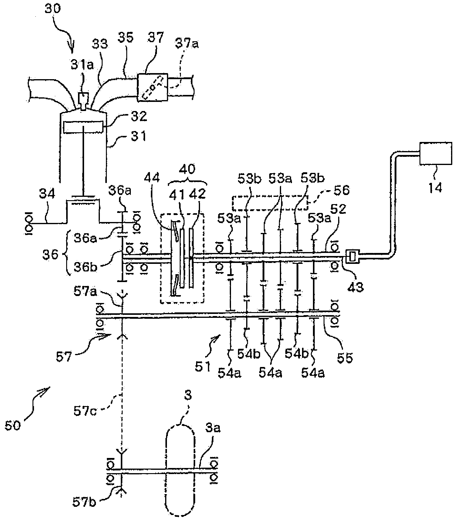
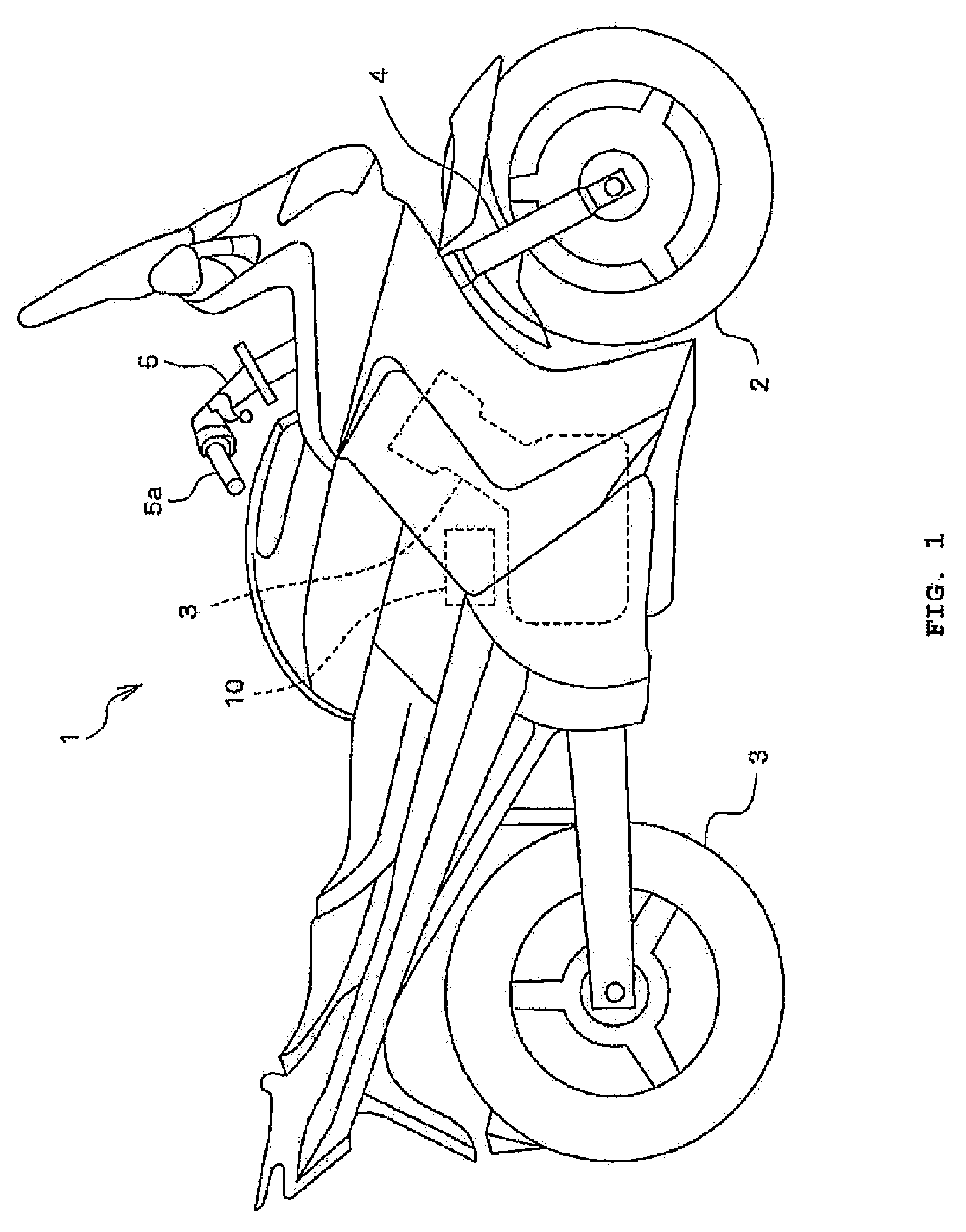
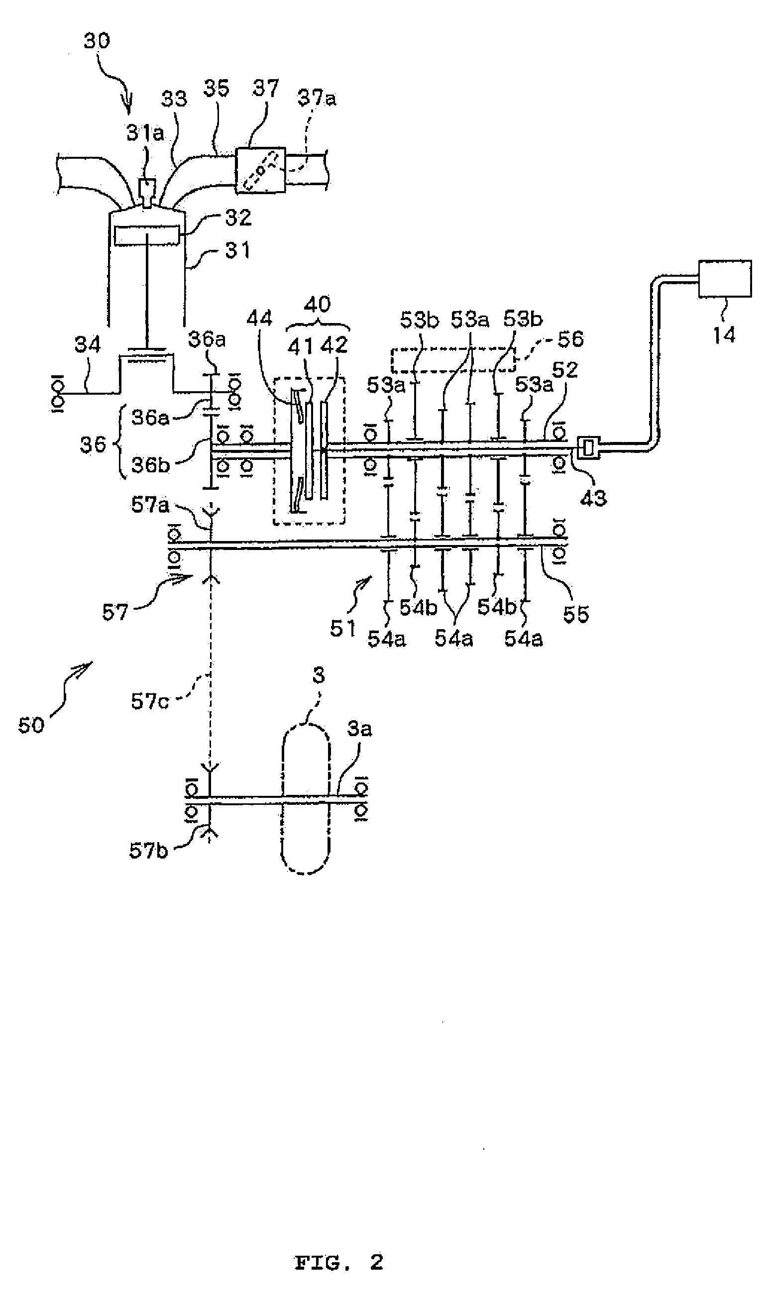
[0025]An embodiment of the present invention is now described with reference to the drawings. FIG. 1 is a side view of a motorcycle 1 provided with a clutch controller 10 as an exemplary embodiment of the invention. FIG. 2 is a schematic view of a mechanism provided on a torque transmission path of motorcycle 1.

[0026]As shown in FIGS. 1 and 2, in addition to clutch controller 10, motorcycle 1 comprises an engine 30, a primary speed reducing mechanism 36, a clutch 40, a secondary speed reducing mechanism 50, a front wheel 2 and a rear wheel 3.

[0027]Front wheel 2 is rotatably supported by lower ends of a front fork 4 extending vertically. Handlebars 5 are connected to the top of front fork 4. An accelerator grip 5a mounted to a right end of handlebars 5 is connected to a throttle valve 37a provided in a throttle body 37 (FIG. 2). Throttle valve 37a is rotated according to rider's accelerator operation, and a certain amount of air, which depends on the rotation amount of throttle valve...


PUM


Abstract

A clutch controller that improves riding comfort when a clutch is engaged. A target torque obtaining section obtains torque that is supposed to be transmitted from a drive-side member of the clutch to a downstream mechanism in a torque transmission path as target transmission torque, the downstream mechanism including a driven-side member of the clutch. An clutch actuator control section actuates a clutch actuator based on the target transmission torque. The target torque obtaining section estimates torque to be transmitted from the drive-side member to the downstream mechanism after the drive-side member and the driven-side member are completely engaged, and obtains the estimated torque as the target transmission torque.

Description

RELATED APPLICATIONS[0001]This application claims the benefit of priority under 35 USC 119 of Japanese patent application no. 2007-043645, filed on Feb. 23, 2007, and Japanese patent application no. 2008-028132, filed on Feb. 7, 2008, which applications are hereby incorporated by reference in their entireties.BACKGROUND OF THE INVENTION[0002]1. Field of the Invention[0003]The present invention relates to control of an engagement state of a clutch by actuating an actuator.[0004]2. Description of Related Art[0005]In a vehicle with a semi-automatic transmission that actuates an actuator to engage or disengage a clutch, the clutch is provided with a drive-side member (for example, a friction disk) that rotates upon receipt of rotational force from a driving source, and a driven-side member (for example, a clutch disk) that is pressed by the drive-side member to operate in conjunction with the drive-side member. The vehicle controls the engagement state of the clutch based on a differenc...

Claims


Application Information

Patent Timeline
Patent Type & Authority Applications(United States)
IPC IPC(8): F16D48/06
CPCF16D48/06F16H2059/147F16D2500/3026F16D2500/30406F16D2500/30412F16D2500/30421F16D2500/3065F16D2500/3067F16D2500/30806F16D2500/3108F16D2500/3144F16D2500/31466F16D2500/50287F16D2500/50684F16D2500/7041F16D2500/70424F16D2500/7044F16H61/682F16H63/46F16H2306/52F16D2500/1117
Inventor MINAMI, KENGO
Owner YAMAHA MOTOR CO LTD
Learn More