
Hydraulic Regenerative Braking System For a Vehicle

a technology of hydraulic regenerative braking and vehicle, which is applied in the direction of fluid actuated drum brakes, hoisting equipment, instruments, etc., to achieve the effect of reducing flow interruptions

Inactive Publication Date: 2008-09-04
WALKER FRANK H
View PDF55 Cites 27 Cited by
  • Summary
  • Abstract
  • Description
  • Claims
  • Application Information

AI Technical Summary

Benefits of technology

[0007]Accordingly, the present invention provides a hydraulic regenerative braking system for a vehicle that conserves space by using one or more flywheel arrangements configured to store energy and provide access to the stored energy.

Problems solved by technology

The high and low pressure accumulators of conventional hydraulic regenerative systems may occupy an undesirable amount of space in a vehicle, making an alternative energy storage system desirable.

Method used


Image

  • Hydraulic Regenerative Braking System For a Vehicle
  • Hydraulic Regenerative Braking System For a Vehicle
  • Hydraulic Regenerative Braking System For a Vehicle

Examples


Embodiment Construction

)

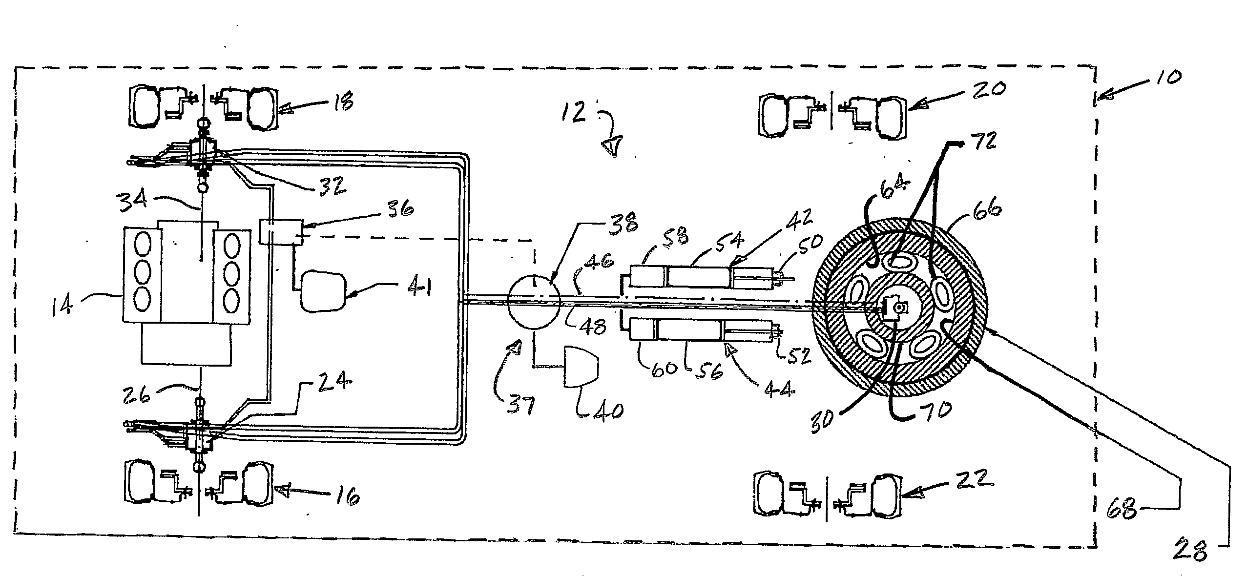
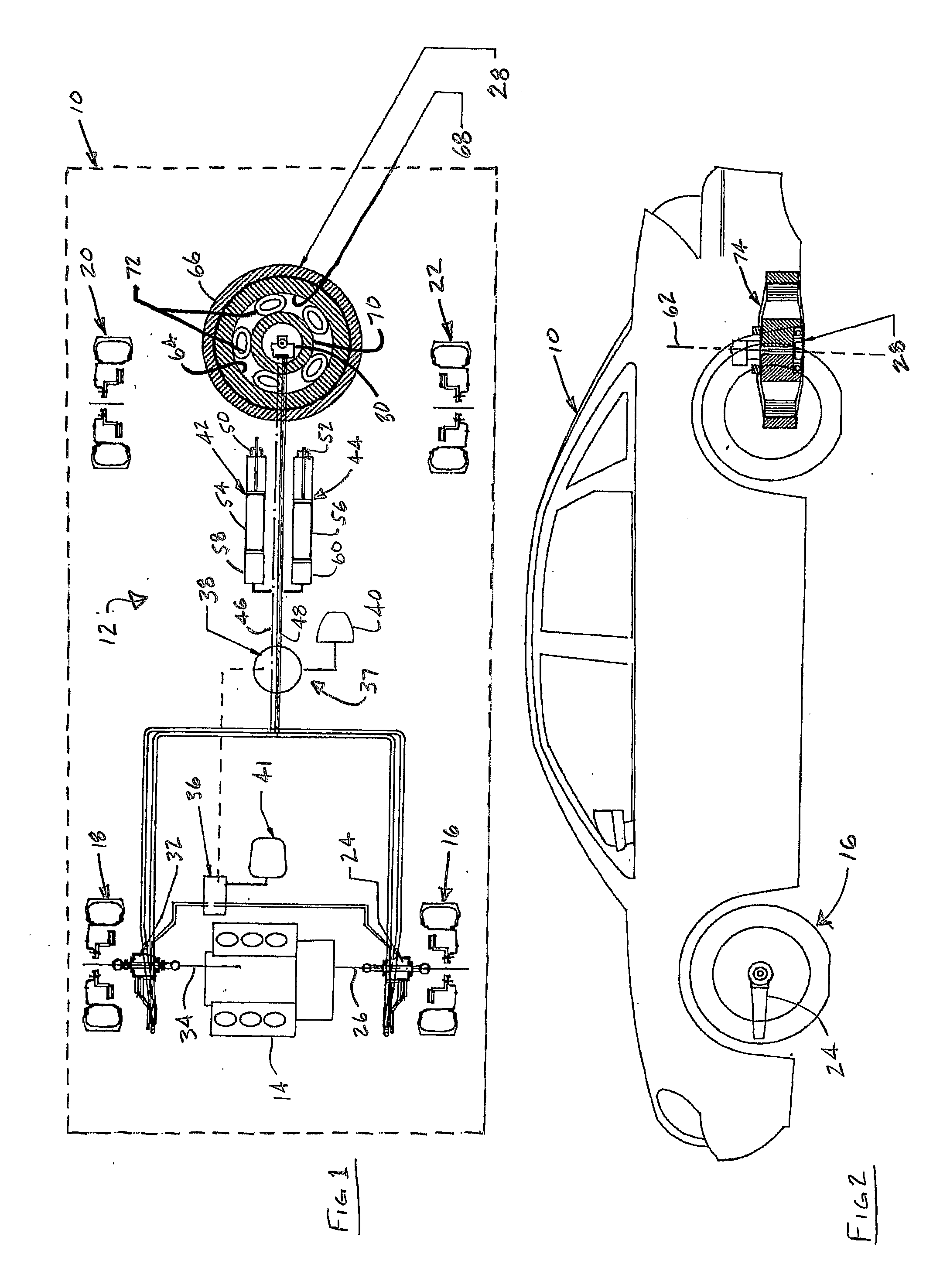
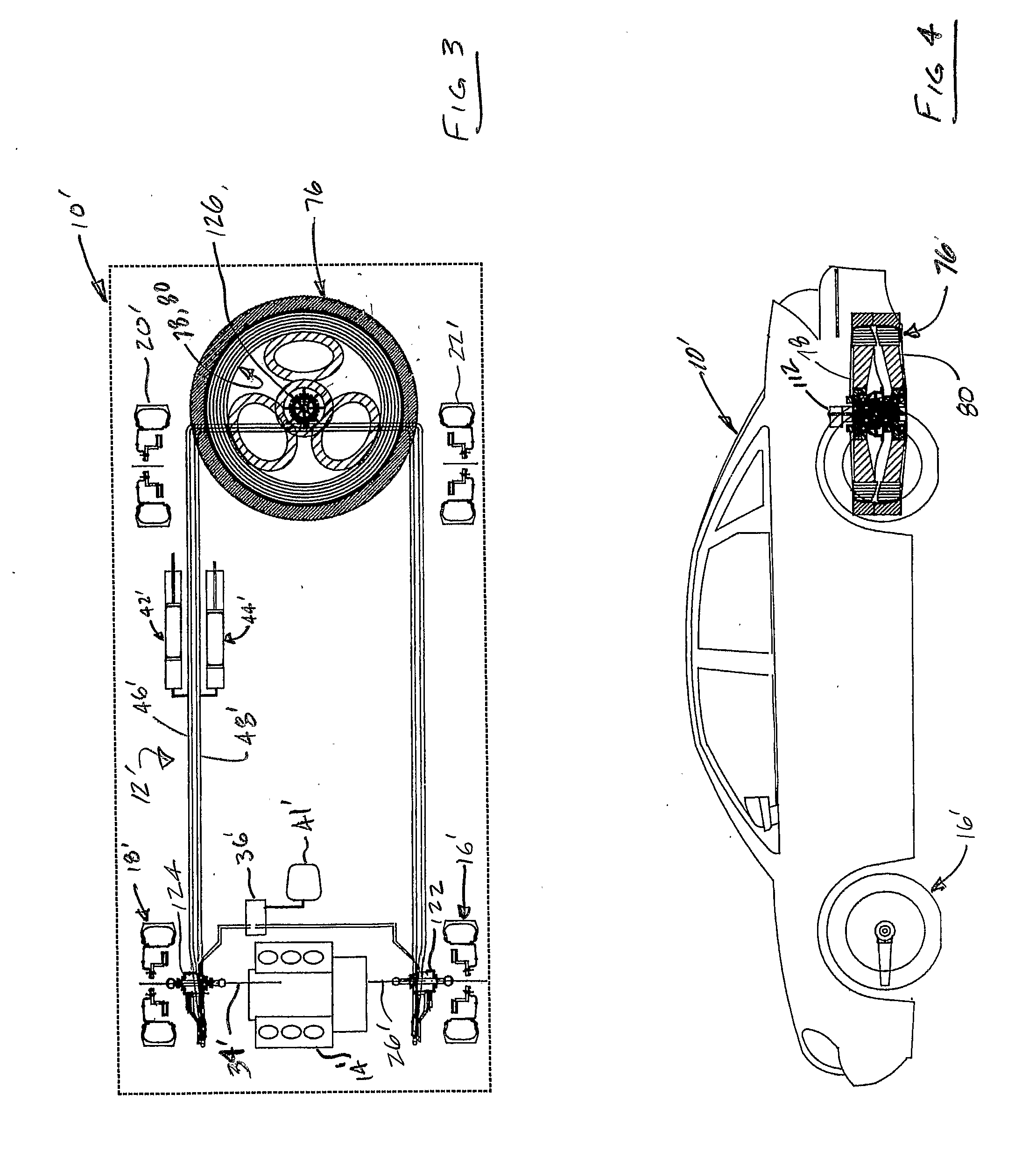
[0045]FIG. 1 shows a vehicle 10 including a hydraulic regenerative braking system 12 in accordance with one embodiment of the present invention. The vehicle 10 also includes an engine 14, and four wheels 16, 18, 20, 22, two of which, the wheels 16, 18, are drive wheels. The regenerative braking system 12 includes a first hydraulic machine, or pump / motor 24. The pump / motor 24 is connected to a shaft, which in the embodiment shown in FIG. 1, is a front axle 26 of the vehicle 10. As explained more fully below, the pump / motor 24 is configured to act as a motor to provide torque to the drive wheel 16, and to capture energy while the vehicle 10 is braking, and provide this energy to a flywheel arrangement 28 in the rear of the vehicle 10.

[0046]A second hydraulic machine, or pump / motor 30, is operatively connected to the flywheel arrangement 28, and is configured to receive fluid from the first pump / motor 24 to operate as a motor to provide torque to the flywheel arrangement 28. The secon...


PUM


Abstract

One embodiment of a hydraulic regenerative braking system for a vehicle having at least one drive wheel includes first (24) and second (32) hydraulic machines operable as pumps or motors. One of the hydraulic machines operates in conjunction with the vehicle drive wheels, while the other hydraulic machine operates in conjunction with a flywheel arrangement (28) to store and receive energy. The hydraulic machines are connected to each other such that when one is operating as a pump, it provides fluid to the other to operate that machine as a motor. A control system is provided to receive inputs related to the operation of the vehicle, and to control the fluid flow through the hydraulic machines.

Description

CROSS-REFERENCE TO RELATED APPLICATIONS[0001]This application claims the benefit of U.S. Provisional Application Ser. No. 60 / 679,549, filed May 11, 2005; U.S. Provisional Application Ser. No. 60 / 684,711, filed May 26, 2005; U.S. Provisional Application Ser. No. 60 / 727,227, filed Oct. 17, 2005; U.S. Provisional Application Ser. No. 60 / 751,467, filed Dec. 19, 2005; U.S. Provisional Application Ser. No. 60 / 754,710, filed Dec. 30, 2005; and U.S. Provisional Application Ser. No. 60 / 760,048, filed Jan. 19, 2006, each of which is hereby incorporated herein by reference.BACKGROUND OF THE INVENTION[0002]1. Field of the Invention[0003]The present invention relates to a hydraulic regenerative braking system for a vehicle.[0004]2. Background Art[0005]It is well known that hydraulic regenerative braking systems promise improved efficiency over electric regenerative systems incorporating a battery. Conventional hydraulic regeneration involves using a pump connected in the vehicle drivetrain as a ...

Claims


Application Information

Patent Timeline
IPC IPC(8): B60T11/12G06F19/00
CPCB60K6/105B60K6/12Y02T10/6208Y02T10/6204B60T1/10Y02T10/62
Inventor WALKER, FRANK H.
Owner WALKER FRANK H
Learn More