
Blind Device Comprising A Damping Mechanism

a blind device and damping mechanism technology, applied in the direction of roofs, superstructure sub-units, building components, etc., can solve the problems of uncontrolled shade take-up, inherent sealing problems, and uncontrolled shade take-up

Inactive Publication Date: 2008-09-04
WEBASTO AG
View PDF6 Cites 14 Cited by
  • Summary
  • Abstract
  • Description
  • Claims
  • Application Information

AI Technical Summary

Benefits of technology

The invention is a shade means that effectively dampens the motion of the shade material when it is unrolled from the take-up roll. This is achieved by using a pressure volume that builds up pressure as the length of shade material is unrolled from the take-up roll. The pressure volume is coupled to the free end of the shade material and a pull is used to move the shade material. The pressure volume can be actuated by a spring force of the take-up roll, and the damping action increases with the speed of the take-up motion. The use of a pressure volume in this way provides several advantages, such as preventing snap-back of the shade, avoiding wear and tear, and being maintenance-free.

Problems solved by technology

Even if provision is made for the length of shade material to be guided as it moves, for example, by a pull being attached to the free end of the length of shade material and being guided in lateral guide rails, uncontrolled take-up of the shade in which the shade snaps back under the action of a spring force has proven disadvantageous, on the one hand, since high take-up speeds can cause damage to part of the shade means, and on the other hand, uncontrolled take-up of the shade due to the associated jerky motion of the shade and the unwanted and often unexpected noise development when the pull strikes a stop are perceived as disturbing by the operator.
Aside from the fact that, in this approach, only rather limited damping can be produced, in the implementation of such a shade system in which a moving component is guided out of a liquid filled chamber, inherent sealing problems arise.
Since the buffer is used only in the very last part of the opening motion of the shade, with buffers, the unduly rapid recoil motion of the shade which often leads to startling of the operator cannot be influenced, and moreover, the impact of the pull or the sliders guiding the pull leads to unwanted noise development and to wear phenomena on the shade means.

Method used


Image

  • Blind Device Comprising A Damping Mechanism
  • Blind Device Comprising A Damping Mechanism
  • Blind Device Comprising A Damping Mechanism

Examples


Embodiment Construction

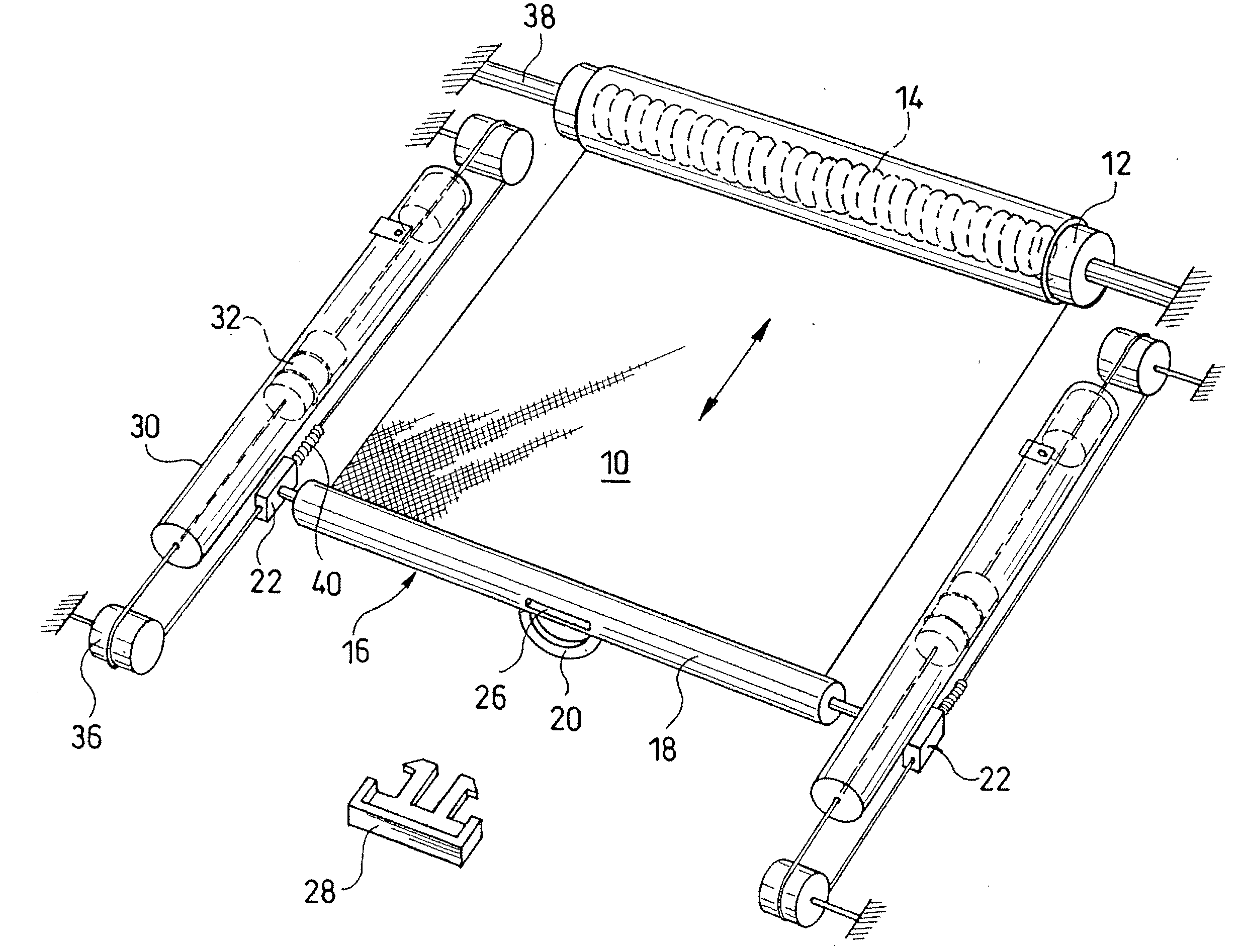
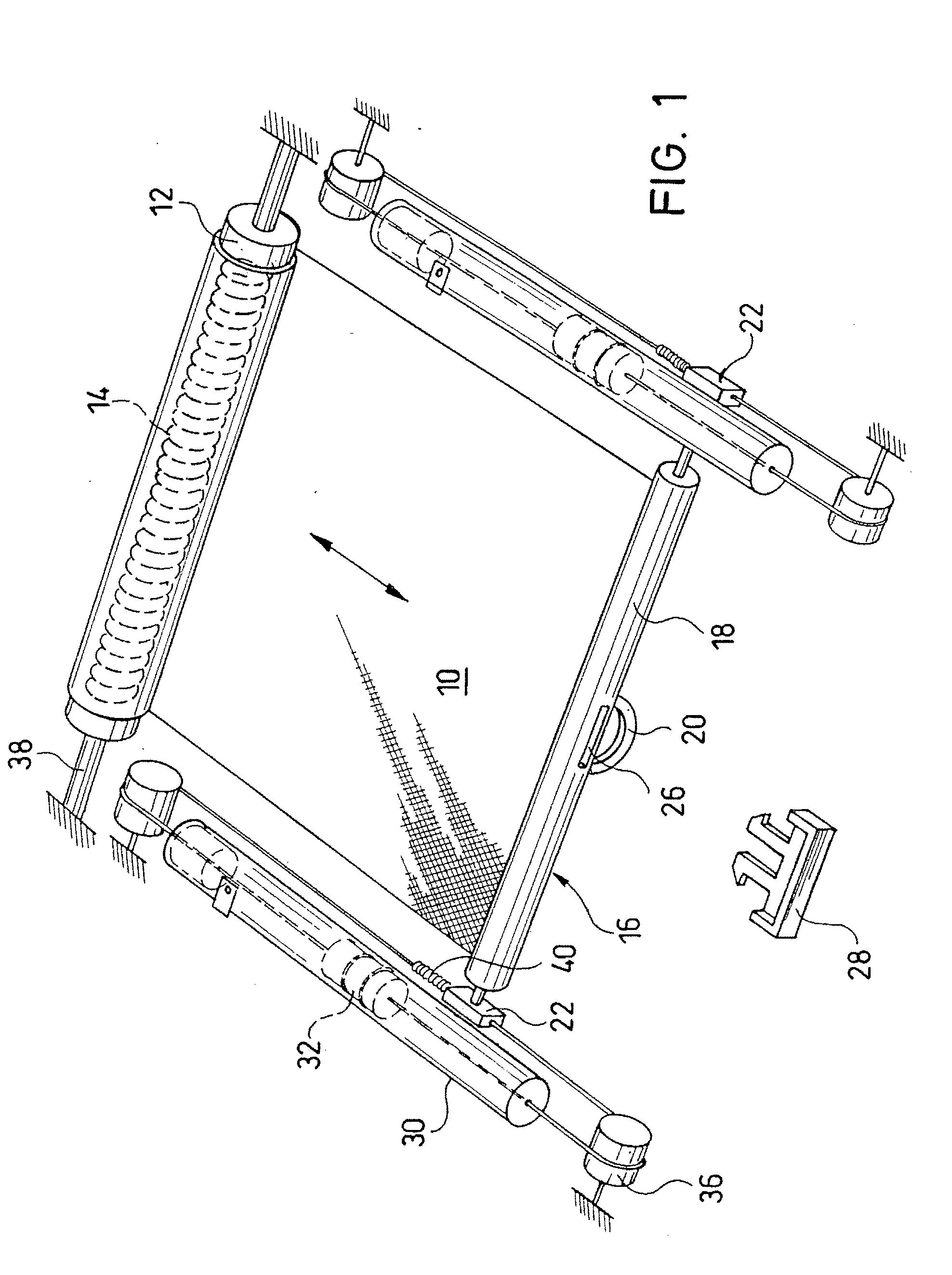
[0038]FIG. 1 shows a shade means in which the length of shade material 10 is taken up onto a take-up shaft 12 which is pretensioned by means of a spring 14 in the take-up direction of the length of shade material 10. The length of shade material 10 can be preferably lengths of fabric which, depending on the application, can also be provided with a light reflecting or heat reflecting layer.

[0039]In the embodiment shown in FIG. 1, there is a pull 18 on the free end 16 of the length of shade material 10 that is provided with a handle 20 for actuation by the operator. Each end of the pull 18 is connected to a slider 22. Sliders 22 are guided in guide rails 24 (such as that shown in FIG. 16) and which are run parallel to the drawing direction of the shade.

[0040]To draw the length of shade material 10, the operator pulls the pull 18 on the handle 20 in a direction away from the take-up shaft 12, as a result of which the length of shade material 10 is unrolled from the take-up shaft 12 aga...


PUM


Abstract

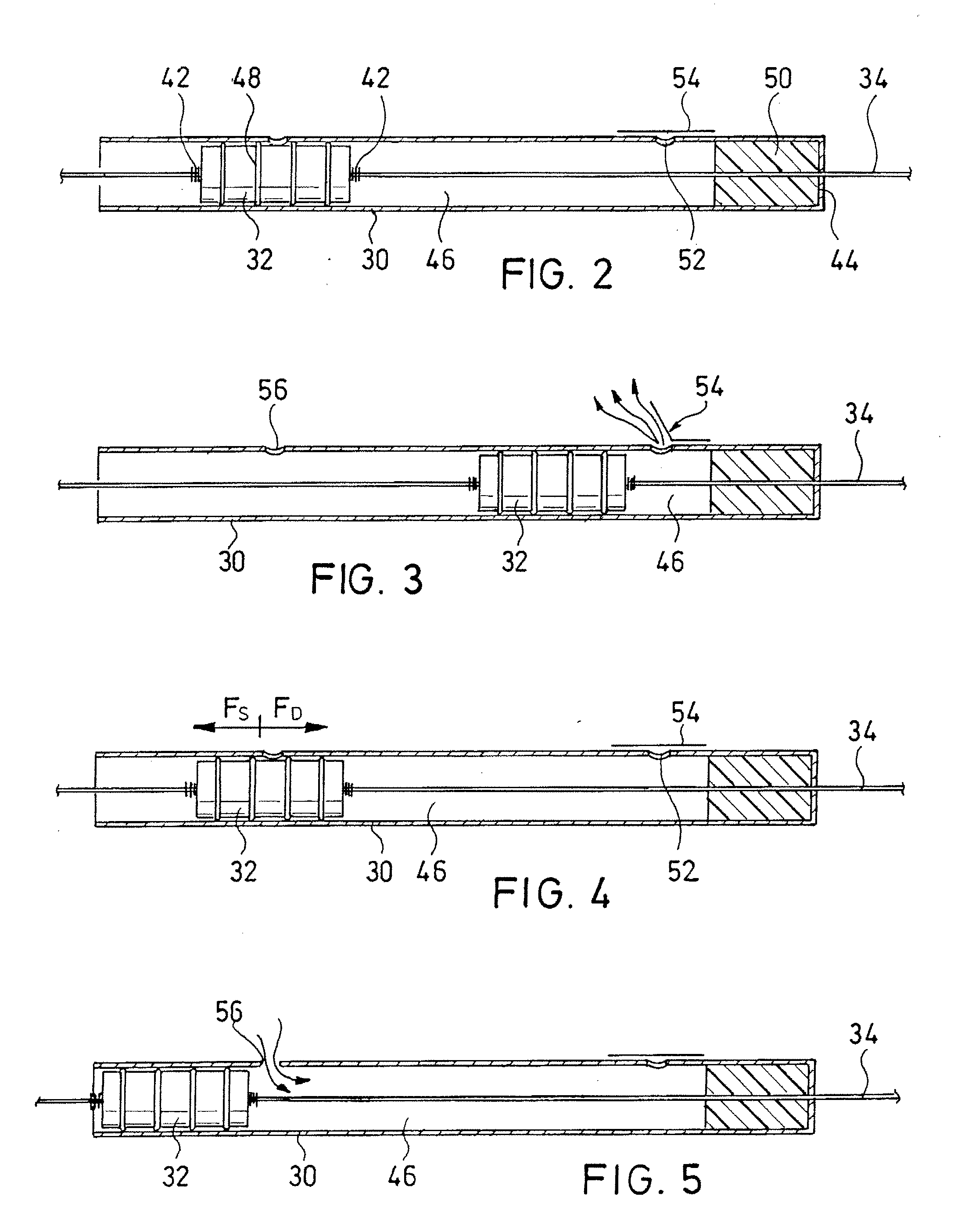
Uncontrolled take-up of a shade and often unexpected noise development are perceived as disturbing by the operator. Therefore, it is provided that a shade arrangement with a length of shade material (10) and a take-up roll (12) to which the length of shade material is attached and which is pretensioned by spring force in the take-up direction of the length of shade, has a pressure volume (46) coupled to the free end (16) of the length of shade material (10) such that, when the length of shade material is unrolled from the take-up shaft (12), a pressure is built up in the pressure volume which, when the length of shade material is released from a position in which it is at least partially unrolled from the take-up roll, the take-up motion of the length of shade is braked.

Description

BACKGROUND OF THE INVENTION[0001]1. Field of the Invention[0002]The invention relates to a shade means with a length of shade material and a take-up roll to which the length of shade material is attached and which is pretensioned by spring force in the take-up direction of the length of shade. Furthermore, this invention also relates to a motor vehicle roof with such a shade arrangement.[0003]2. Description of Related Art[0004]Shade means of the initially named type are used for numerous applications, especially for shading purposes, for example, on buildings or in automotive construction, especially as cargo space covers and trunk covers, and also as covers, for example, for cabinets or chests.[0005]To activate such a shade arrangement, the length of shade material is unrolled from the take-up roll against the force of a return spring and is fixed in at least the partially unrolled state, for example, hung. In order to then uncover the shaded area, the free end of the length of sha...

Claims


Application Information

Patent Timeline
Patent Type & Authority Applications(United States)
IPC IPC(8): E06B9/56B62D25/06B60J7/043E06B9/42E06B9/60E06B9/68E06B9/80
CPCB60J7/0015E06B2009/808E06B9/80E06B9/42
Inventor BERGMILLER, ALEXANDEROBERHAUS, PETERKOELBL, MICHAELRUDOLPH, THOMASSCHULZ, HORST-MARTINADLHOCH, CHRISTIANGLASL, SEBASTIAN
Owner WEBASTO AG
Learn More