Electro-Optic Lenses Employing Resistive Electrodes

a technology of resistive electrodes and optical lenses, applied in the field of optical lenses, can solve the problems of affecting binocular depth perception, bulky and costly spectacles, and poor optical performan

Inactive Publication Date: 2008-09-04
MEREDITH GERALD
View PDF36 Cites 59 Cited by
  • Summary
  • Abstract
  • Description
  • Claims
  • Application Information

AI Technical Summary

Benefits of technology

[0005]Provided is an electro-optic device comprising: a liquid crystal layer between a pair of opposing transparent substrates; a resistive patterned electrode set positioned between the liquid crystal layer and the inward-facing surface of the first transparent substrate; and a conductive layer between the liquid crystal layer and the inward-facing surfa

Problems solved by technology

However, the mechanical approach makes the spectacle bulky and costly.
Furthermore, these optical techniques do not work well when the pupil is small, since the iris blocks the beam that passes through the annular portion of the

Method used


Image

  • Electro-Optic Lenses Employing Resistive Electrodes
  • Electro-Optic Lenses Employing Resistive Electrodes
  • Electro-Optic Lenses Employing Resistive Electrodes

Examples


Embodiment Construction

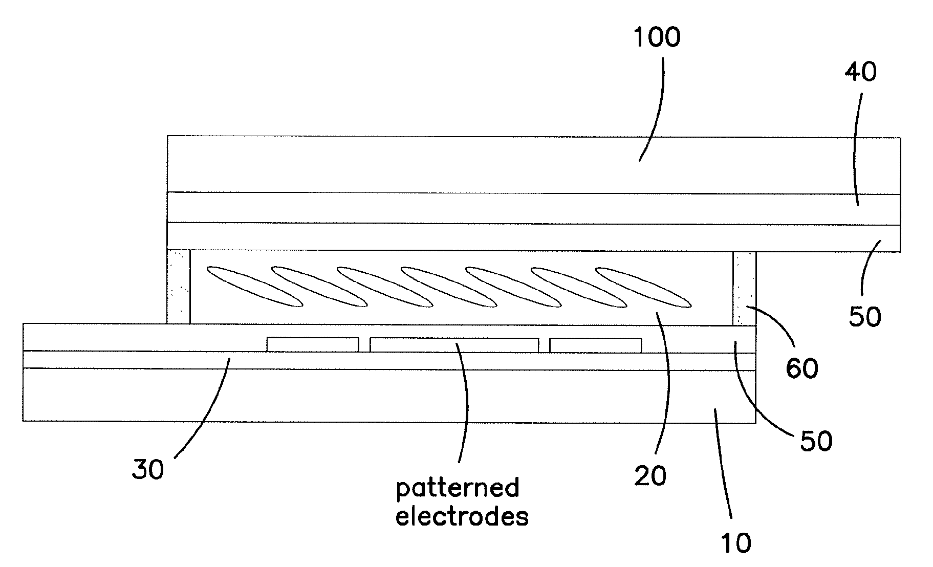
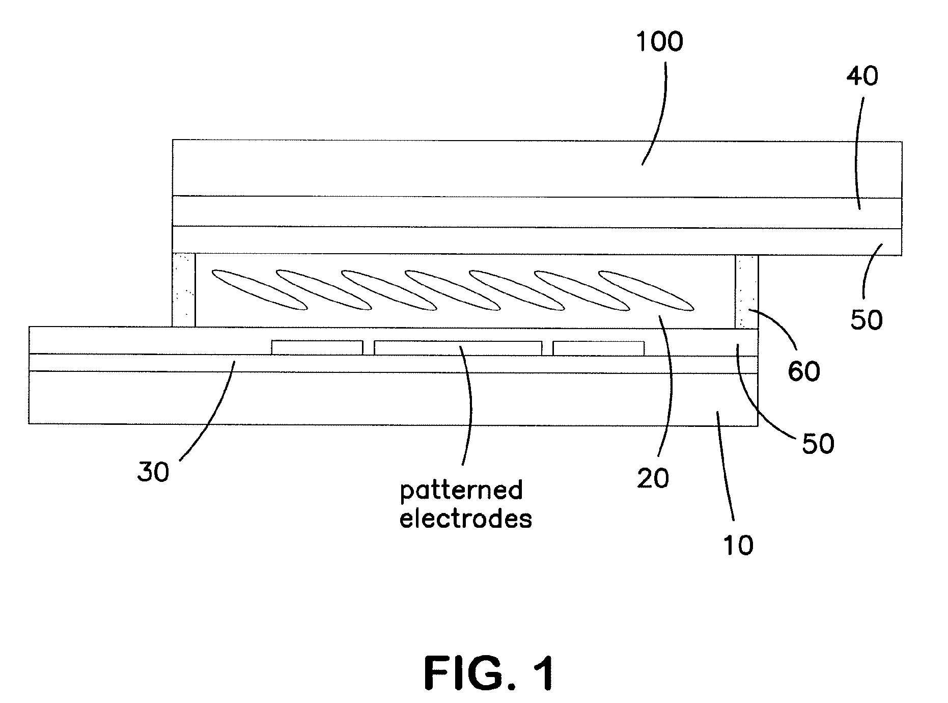
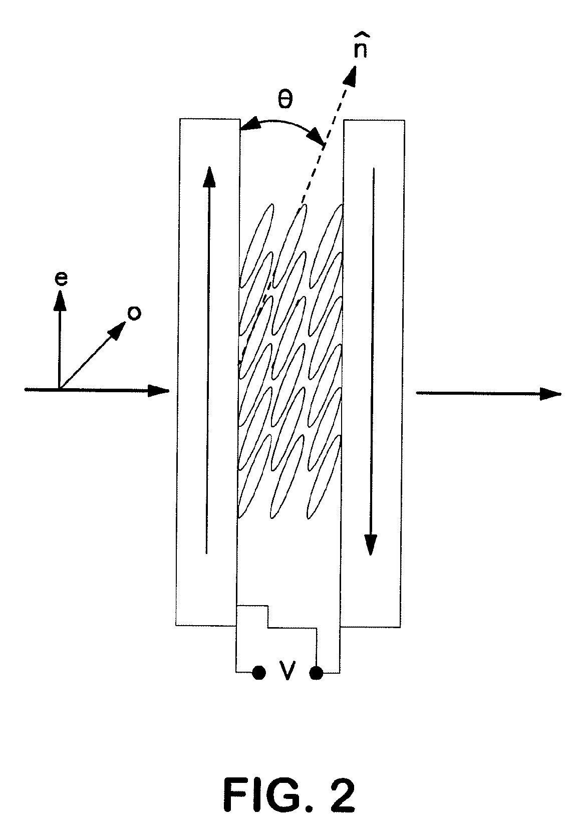
[0014]The following description provides non-limiting details of constructing the electro-optic lenses of the present invention. This invention provides electro-optic lenses filled with liquid crystal material that can be realigned in an electric field. The lenses function as diffractive-optical-elements (DOE). DOE are the result of applying voltages across a thin liquid-crystal layer which responds by altering the director-orientation field and creates nonuniform refractive-index patterns which then lead to a nonuniform phase-transmission-function (PTF) across the face of the cell. In the invention herein, accurate control of the PTF to create the desired DOE is achieved by applying the desired voltage drop across the resistive patterned electrode set.

[0015]As used herein, “resistive patterned electrode set” is one or more areas of electrically conductive material (electrodes) that are electrically separated from each other and to which a desired voltage drop can be applied. If the...


PUM


Abstract

Provided is an electro-optic device comprising: a liquid crystal layer between a pair of opposing transparent substrates; a resistive patterned electrode set positioned between the liquid crystal layer and the inward-facing surface of the first transparent substrate; and a conductive layer between the liquid crystal layer and the inward-facing surface of the second transparent substrate, wherein the conductive layer and resistive patterned electrode set are electrically connected, and wherein said resistive patterned electrode set comprises one or more electrically-separated electrodes, wherein the desired voltage drop is applied across each electrode to provide the desired phase retardation profile.

Description

CROSS-REFERENCE TO RELATED APPLICATIONS[0001]This application claims the benefit of U.S. Provisional Application No. 60 / 824,325, filed Sep. 1, 2006, which is incorporated by reference herein.BACKGROUND OF THE INVENTION[0002]The present invention is in the field of optical lenses. Ophthalmic lenses with fixed focusing properties have been widely used as spectacles and contact lenses to correct presbyopia and other conditions. Ophthalmic lenses are most useful if they have adjustable focusing power (i.e., the focusing power is not static). Adjustable focusing power provides the eye with an external accommodation to bring objects of interest at different distances into focus.[0003]Adjustable focusing power can be achieved using a mechanical zoom lens. However, the mechanical approach makes the spectacle bulky and costly. Different optical techniques have been exploited in bifocal lenses to allow both near and distance vision. For example, the user may have lenses providing different fo...

Claims


Application Information

Patent Timeline
IPC IPC(8): G02F1/1333G02F1/1343
CPCG02C7/083G02F1/134309G02F2203/28G02F1/292G02F1/13439G02B26/00G02F1/133H01L21/00
Inventor MEREDITH, GERALD
Owner MEREDITH GERALD
Why Eureka
Try Eureka