
Easily disassembling cooling apparatus

Inactive Publication Date: 2008-09-04
CHEMTRON RES
View PDF2 Cites 13 Cited by
  • Summary
  • Abstract
  • Description
  • Claims
  • Application Information

AI Technical Summary

Benefits of technology

[0008]One particular aspect of the present invention is to provide an easily disassembling cooling apparatus that can be installed on the circuit board and electronic elements of an electronic device. Its structure is simple. No welding is required when assembling the cooling apparatus. The assembling time is reduced, a lead-free manufacturing process is adopted, and the electronic elements are cooled reliably.
[0011]The present invention has the following characteristics. When the cooling apparatus of the present invention is assembled, the welding process is not required. The electronic elements can be cooled, the assembling time is reduced, and a lead-free manufacturing process is adopted.

Problems solved by technology

Although the cooling apparatus of the prior art can dissipate heat generated by the electronic elements, the heat-absorbing module still needs to be welded to the heat pipes.
Furthermore, it is inconvenient for the assembler.

Method used


Image

  • Easily disassembling cooling apparatus
  • Easily disassembling cooling apparatus
  • Easily disassembling cooling apparatus

Examples


first embodiment

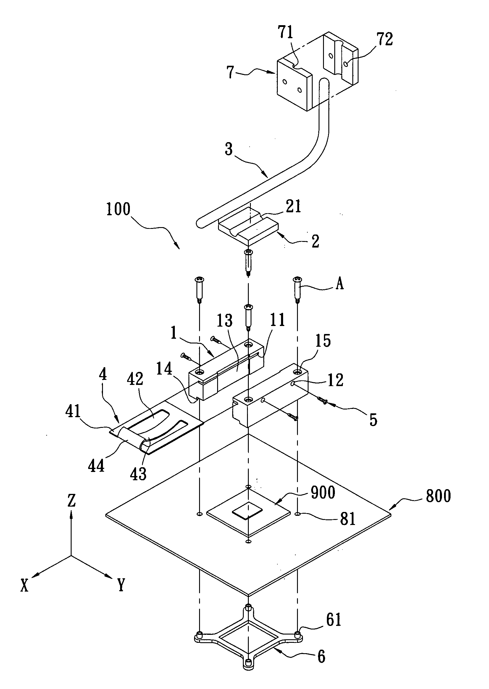
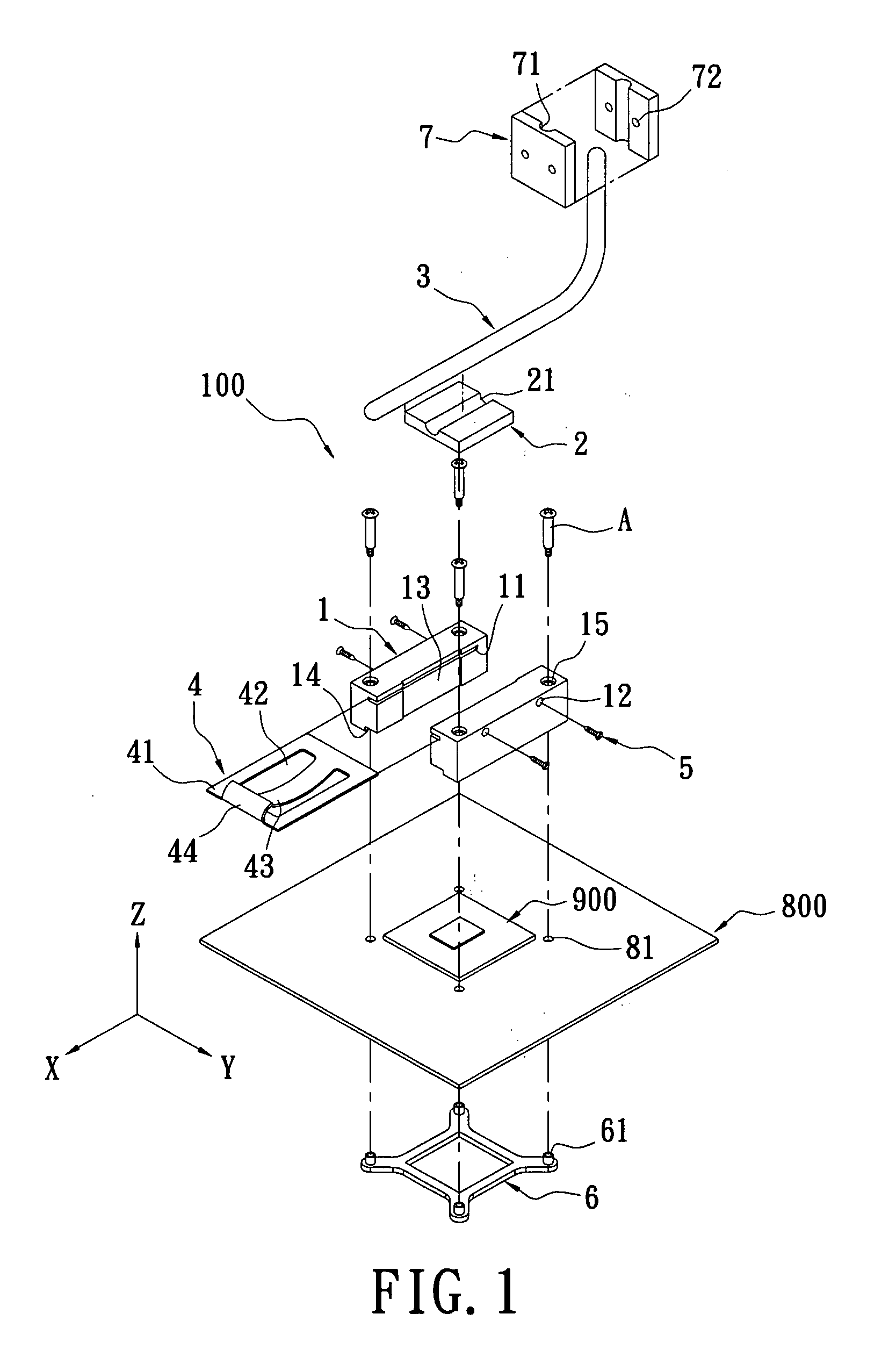
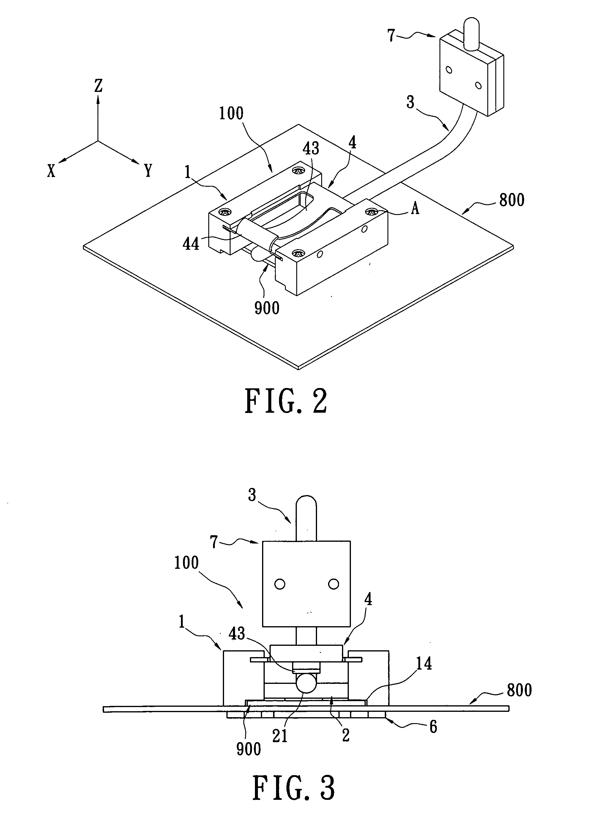
[0025]Reference is made to FIG. 1, which shows the easily disassembling cooling apparatus of the present invention. The cooling apparatus 100 can be assembled with the circuit board 800 of an electronic device. The circuit board 800 is installed with an electronic element 900, such as a CPU, that will generate heat when the electronic element 900 is operating. The cooling apparatus 100 includes a pair of fastening blocks 1, a heat conducting block 2, at least one heat pipe 3, a fastening plate 4, and a plurality of locking elements 5.

[0026]The quantity of the fastening blocks 1 is two, and the pair of fastening blocks 1 are symmetrical. The pair of fastening blocks 1 are made of metal or plastic. One inner side surface of each of the pair of fastening blocks 1 that is close to the upper side has a horizontal track slot 11 along the X-coordinate and a plurality of locking holes 12 along the Y-coordinate that respectively link with the track slot 11.

[0027]The inner side surface of eac...

second embodiment

[0039]FIGS. 4 and 5 show the easily disassembling cooling apparatus of the present invention. In this embodiment, the two opposite side edges of the body 41 of the fastening plate 4 further have a plurality of tooth portions 411. The locking element 5 is a stopping screw that has a screw rod 51, a steel ball 52 installed in the screw rod 51, and a spring 53 installed in the screw rod 51 and flexibly pressing the steel ball 52. When the two side edges of the fastening plate 4 form the tooth portions 411 and the screw rod 51 of the stopping screw is screwed in the locking hole 12 to make the steel ball 52 contact against the base portion (tooth valley) of two adjacent tooth portions 411, the steel ball 52 flexibly contacts against the front edge of the fastening plate 4 by utilizing the flexible force of the sparing 53 to prevent the fastening plate 4 from loosing. Thereby, the assembling process is finished.

[0040]When the cooling apparatus is disassembled, a process that is inverse t...

fifth embodiment

[0043]FIG. 8 shows the easily disassembling cooling apparatus of the present invention (also referring to FIG. 1). A guiding slanted surface 16 is formed at the upper side of the inner side surface of the pair of the fastening blocks 1 along the X-coordinate and the Z-coordinate. The guiding slanted surface 16 is located above the track slot 11. By using the guiding slanted surface 16, the fastening plate 4 is embedded into the track slot 11 from top to bottom along the Z-coordinate.

[0044]When the fastening block 1 has the guiding slanted surface 16, there are two methods to assemble the fastening plate 4. One method is to slide the fastening plate 4 into the track slot 11 along the X-coordinate (that is parallel to the track slot 11) so that the fastening plate 4 is assembled between the pair of the fastening blocks 1. The second method is to embed the fastening plate 4 into the track slot 11 from the guiding slanted surface 16 and along the Z-coordinate (that is vertical to the tr...


PUM


Abstract

An easily disassembling cooling apparatus is assembled onto a circuit board. The circuit board has an electronic element. The cooling apparatus includes a pair of fastening blocks, one or two heat conducting blocks, a heat pipe, a fastening plate, and a plurality of locking elements. The fastening blocks are fastened onto the circuit board and each has a track slot. The heat conducting block is installed between the fastening blocks and contacts the electronic element. One end of the heat pipe is installed with the heat conducting block. The fastening plate is installed in the track slots of the fastening blocks, and has a flexible arm that flexibly presses onto the heat pipe. Each of the locking elements respectively is combined with the fastening block. Thereby, the welding process is not required in the assembling process. The electronic element is reliably cooled, and the assembling time is reduced.

Description

BACKGROUND OF THE INVENTION[0001]1. Field of the Invention[0002]The present invention relates to a cooling apparatus. In particular, this invention relates to a cooling apparatus that is installed on an electronic device.[0003]2. Description of the Related Art[0004]The circuit board of an electronic device has a variety of electronic elements, such as a central processing unit (CPU). As the electronic industry has been developed, the operation speed of CPUs rapidly increases and thus the heat generated by CPUs also increases. Because electronic devices are generally enclosed by a housing, the temperature inside the housing rises substantially. Therefore, a cooling apparatus is required for the electronic elements in order to make the electronic device operate normally.[0005]A variety of cooling apparatuses are developed for electronic elements. For example, Taiwan patent No. M288399 discloses a cooling apparatus. The cooling apparatus includes a cooling module, a plurality of heat p...

Claims


Application Information

Patent Timeline
IPC IPC(8): H05K7/20
CPCH01L23/4006H01L23/4093H01L23/427H01L2023/4056H01L2023/4081H01L2924/0002H01L2023/4087H01L2924/00
Inventor LIN, YU-CHENG
Owner CHEMTRON RES
Features
  • Generate Ideas
  • Intellectual Property
  • Life Sciences
  • Materials
  • Tech Scout
  • Unparalleled Data Quality
  • Higher Quality Content
  • 60% Fewer Hallucinations
Learn More