
Receiver For Wireless Communications

a wireless communication and receiver technology, applied in the direction of discrete pre-tuned circuits, electrical appliances, transmission, etc., can solve the problems of many inability to adopt many state-of-the-art dsp techniques in digital domain, and distortions in user signals that often exceed the allowable level, etc., to achieve ideal in-band distortion, component size and cost, and insertion loss

Inactive Publication Date: 2008-09-04
KONINKLIJKE PHILIPS ELECTRONICS NV
View PDF8 Cites 16 Cited by
  • Summary
  • Abstract
  • Description
  • Claims
  • Application Information

AI Technical Summary

Benefits of technology

[0012]An object of the present invention is to provide a bandpass sampling receiver for use in mobile communication systems. In this bandpass sampling receiver, the analog RF signal received at the antenna is filtered by an RF processing link constructed by multiple cascaded RF filters, thus the bandpass sampling receiver can satisfy the requirement for selectivity, and attain ideal in-band distortion, insertion loss, component size and cost as well.
[0013]Another object of the present invention is to provide a bandpass sampling receiver for use in mobile communication systems. In this bandpass sampling receiver, the analog RF signal received at the antenna is filtered by multiple RF processing links operating in different bands and individually constructed by multiple cascaded RF filters, thus the bandpass sampling receiver can satisfy the selectivity requirement when working in multi-band and multi-mode or wide frequency band.
[0014]The third object of the present invention is to provide a bandpass sampling receiver for use in mobile communication systems. In this bandpass sampling receiver, the analog RF signal received at the antenna is filtered by a tunable RF processing link constructed by multiple cascaded RF filters, thus the bandpass sampling receiver can satisfy the selectivity requirement when working in multi-band and multi-mode or wide frequency band.

Problems solved by technology

The conventional receiver performs most processing work o n RF signals in analog domain, and thus can't adopt many state-of-the-art DSP techniques in digital domain.
When the analog RF signal received at the antenna is bandpass sampled by the bandpass sampling receiver, the out-of-band interference out of the frequency band of the desired user signal will fold into the frequency band of the user signal and cause distortion in the user signal.
The power of said out-of-band interference is usually very strong, so the distortion caused in the user signal often exceeds the allowable level.
However, it's still extremely difficult for a n RF filter to have such a high selectivity with ideal in-band distortion and reasonable component size at acceptable cost.
Therefore, application of bandpass sampling at radio frequency is very limited and exists mainly in theoretical analysis.

Method used


Image

  • Receiver For Wireless Communications
  • Receiver For Wireless Communications
  • Receiver For Wireless Communications

Examples


Embodiment Construction

[0028]To satisfy the selectivity requirement for the RF filters of the bandpass sampling receiver, a method in an embodiment of the present invention is to adopt N cascaded RF filters with the same selectivity. Assumed that the required total attenuation of the out-of-band interference is A0, if each RF filter can attenuate the interference by A0 / N, N cascaded RF filters can totally attenuate the out-of-band interference by A0.

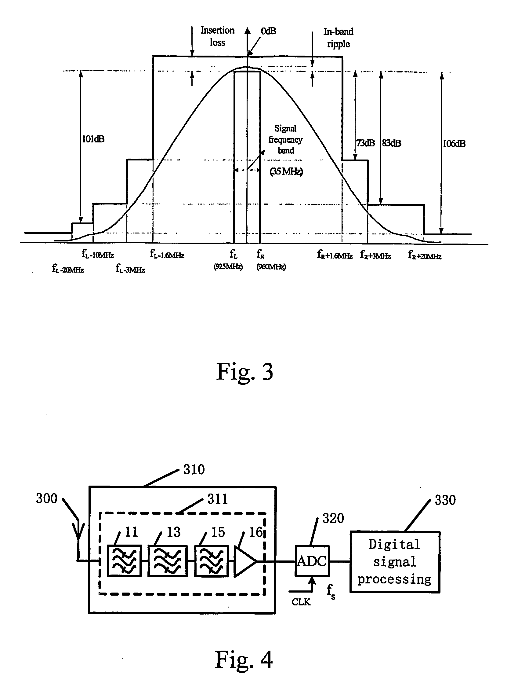
[0029]FIG. 4 illustrates the proposed bandpass sampling receiver with a plurality of cascaded RF filters. As shown in the figure, RF filtering and amplifying unit 310 of the bandpass sampling receiver is composed of an RF processing link 311, and the RF processing link 311 comprises cascaded RF filters 11, 13, 15 and LNA 16. When the bandpass sampling receiver starts to work, antenna unit 300 receives analog RF signal from the radio medium and sends it to RF processing link 311 in RF filtering and amplifying unit 310. In RF processing link 311, the analog RF s...


PUM


Abstract

An RF filtering and amplifying apparatus is proposed, comprising: a plurality of RF filters, connected with each other in a manner of cascade, for filtering the received radio signal level by level; a LNA (low noise amplifier), for amplifying the filtered signal to output an amplified and filtered signal. The RF filtering and amplifying apparatus in the present invention can not only meet the requirement for the selectivity of the filters, but also achieve desirable in-band distortion and insertion loss meanwhile.

Description

FIELD OF THE INVENTION[0001]The present invention relates generally to a bandpass sampling receiver for use in wireless communication systems, and more particularly, to a bandpass sampling receiver whose RF circuit is constructed by multiple cascaded RF filters.BACKGROUND ART OF THE INVENTION[0002]Receivers play a important role in wireless communications, receiving RF signal from radio space at the antenna and converting it into baseband digital signal centered to zero frequency so that the desired user signal satisfying the BER (Bit Error Rate) requirement can be recovered through further baseband processing.[0003]FIG. 1 displays a widely used conventional super heterodyne receiver. As FIG. 1 shows, antenna unit 10 sends the receive d analog RF signal to RF filter 20. RF filter 20 bandpass filters the analog RF signal so that the portion of the analog RF signal in the frequency band of the user signal can pass whilst the out-of-band interference far away from the frequency band of...

Claims


Application Information

Patent Timeline
IPC IPC(8): H04B1/10H03J5/24H04B1/16H04B1/18H04B1/40
CPCH03J5/244H04B1/1638H04B1/1036H04B1/406H04B1/0067H04B1/18
Inventor QIAN, XUECHENG
Owner KONINKLIJKE PHILIPS ELECTRONICS NV
Learn More