Electrohydraulic Torque Transfer Device

a technology of electric motor and torque transfer, which is applied in the direction of control devices, clutches, non-mechanical actuator clutches, etc., can solve the problem of system cost prohibitive in some four-wheel drive applications

Active Publication Date: 2008-09-04
AMERICAN AXLE & MFG
View PDF39 Cites 27 Cited by
  • Summary
  • Abstract
  • Description
  • Claims
  • Application Information

AI Technical Summary

Benefits of technology

[0003]Due to increased demand for four-wheel drive vehicles, many power transmission systems are typically being incorporated into vehicle driveline applications for transferring drive torque to the wheels. Many vehicles include a power transmission device operably installed between the primary and secondary drivelines. Such power transmission devices are typically equipped with a torque transfer mechanism for selectively transferring drive torque from the primary driveline to the secondary driveline to establish a four-wheel drive mode of operation. At least one known torque transfer mechanism includes a dog-type lock-up clutch that may be selectively engaged for rigidly coupling the secondary driveline to the primary driveline when the vehicle is operated in four-wheel drive mode. Drive torque is delivered only to the primary driveline when the lock-up clutch is released and the vehicle operates in a two-wheel drive mode.

Problems solved by technology

For example, the size, weight and packaging requirements of the power transmission device may make such systems cost prohibitive in some four-wheel drive applications.

Method used


Image

  • Electrohydraulic Torque Transfer Device
  • Electrohydraulic Torque Transfer Device
  • Electrohydraulic Torque Transfer Device

Examples


Embodiment Construction

[0019]The following description of the preferred embodiment(s) is merely exemplary in nature and is in no way intended to limit the disclosure, its application, or uses.

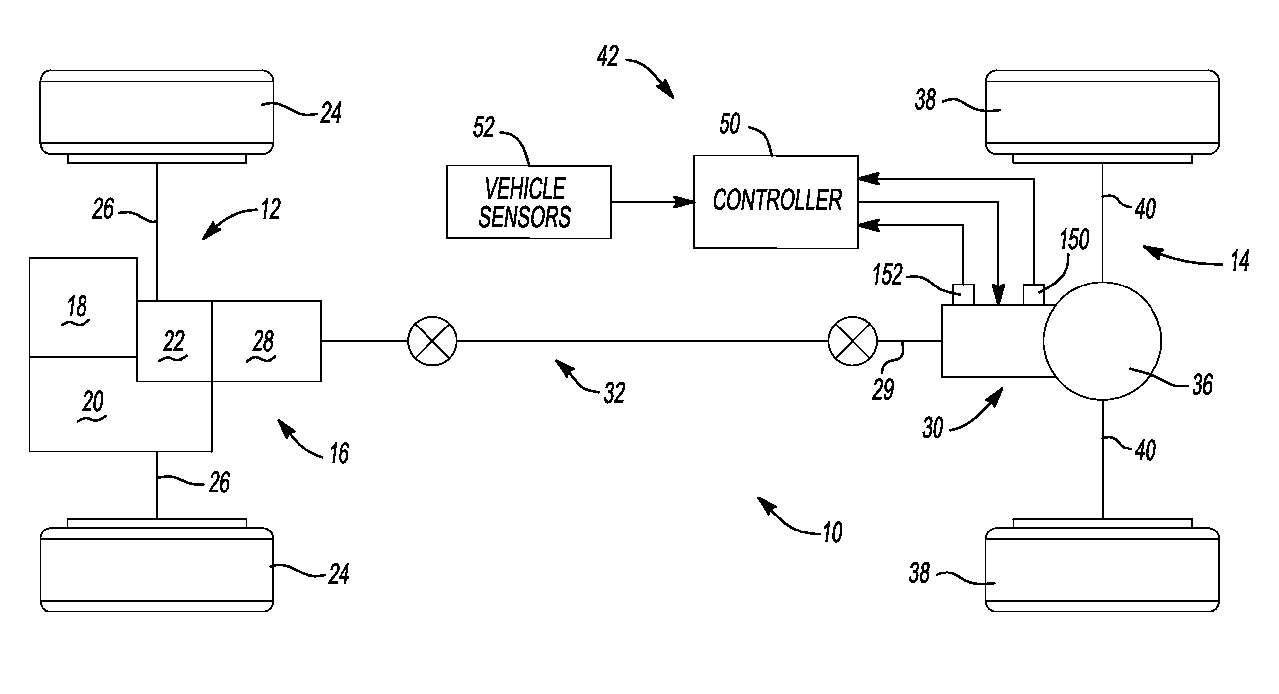
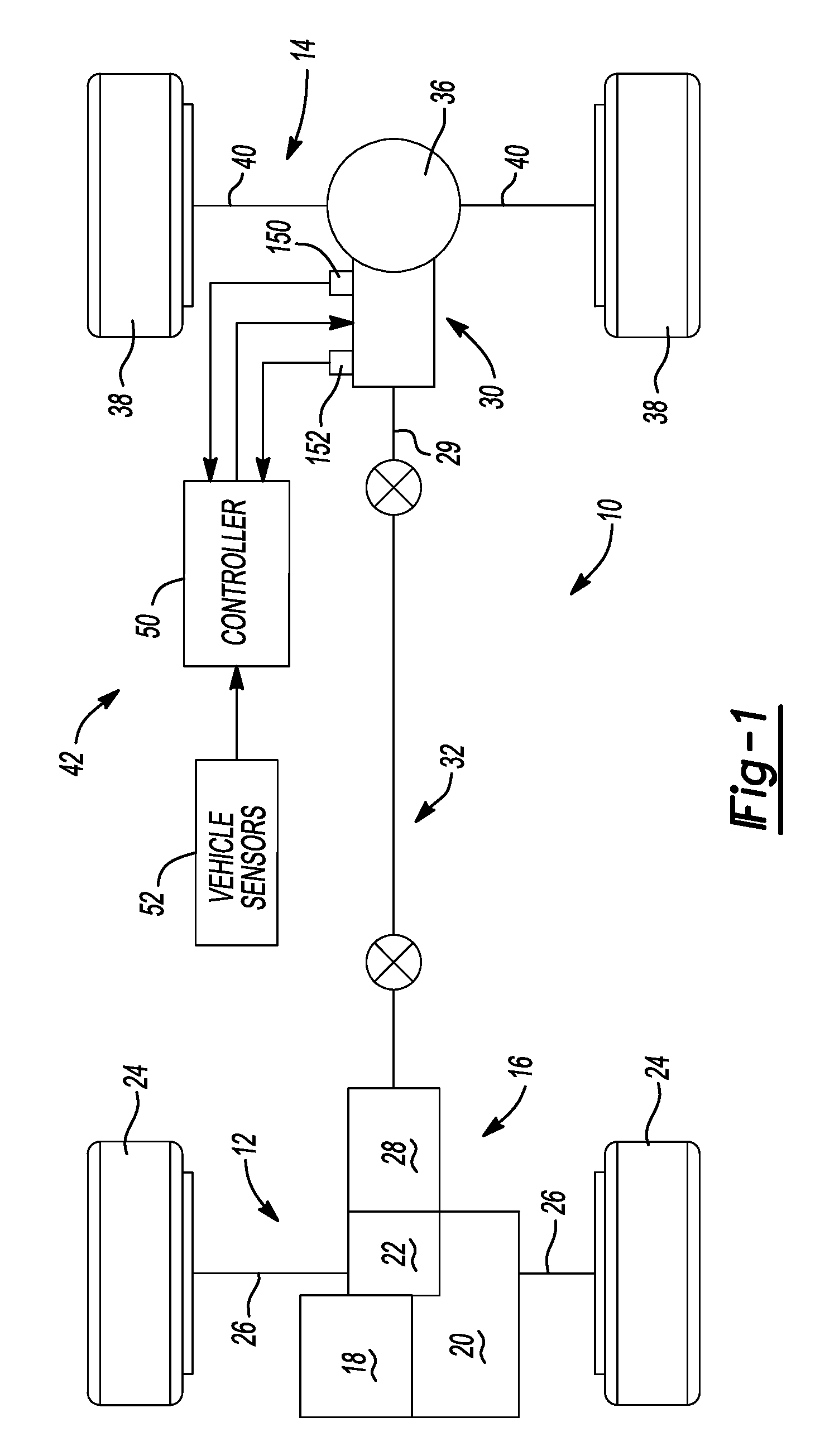
[0020]The present disclosure is directed to a power transmission device that may be adaptively controlled for modulating the torque transferred between a rotatable input member and a rotatable output member. The torque transfer mechanism may be useful within motor vehicle drivelines as a stand-alone device that may be easily incorporated between sections of propeller shafts, directly coupled to a driving axle assembly, or other in-line torque coupling applications. In particular, the torque transfer mechanism may form a part of an axle equipped with an electronically controlled limited slip differential. Accordingly, while the present disclosure is hereinafter described in association with a specific structural embodiment for use in a driveline application, it should be understood that the arrangement shown and descr...


PUM


Abstract

A power transmission device includes an actuator having an electric motor driving a pump to supply pressurized fluid to a piston acting on a friction clutch to transfer torque between rotatable input and output members. In one instance, a valve between the pump outlet and the piston selectively traps pressurized fluid acting on the piston without continued energization of the electric motor. A gerotor may be formed from a material having a first coefficient of thermal expansion and a housing formed from a material having a second lower coefficient of thermal expansion to vary pump component clearances as the viscosity of the pumped fluid changes with changes in temperature. A method of controlling the power transmission device includes defining a correlation between pump speed, fluid temperature and fluid pressure, determining fluid temperature, determining pump speed, and rotating the pump to transfer a predetermined quantity of torque.

Description

CROSS-REFERENCE TO RELATED APPLICATIONS[0001]This application is a continuation-in-part of U.S. patent application Ser. No. 11 / 201,468 filed on Aug. 11, 2005. The disclosure of the above application is incorporated herein by reference.BACKGROUND AND SUMMARY[0002]The present disclosure relates generally to a power transmission device operable to selectively transfer torque between first and second sets of drivable wheels of a vehicle. More particularly, the present disclosure is directed to a power transmission device adapted for use in motor vehicle driveline applications having an actuator including an electric motor drivably coupled to a gerotor for providing pressurized fluid to a piston acting on a friction clutch.[0003]Due to increased demand for four-wheel drive vehicles, many power transmission systems are typically being incorporated into vehicle driveline applications for transferring drive torque to the wheels. Many vehicles include a power transmission device operably ins...

Claims


Application Information

Patent Timeline
Patent Type & Authority Applications(United States)
IPC IPC(8): F16D48/06F16D25/00
CPCB60K17/351B60K23/0808F16D25/0638F16D25/083F16D48/02Y10T477/6425F16D2500/10431F16D2500/3024F16D2500/30406F16D2500/30803F16D48/066F16D2500/1024F16D2500/1045F16D2500/3021F16D2500/3056F16D2500/3069F16D2500/3101F16D2500/3108F16D2500/3166F16D2500/50816F16D2500/5108F16D2500/70217F16D2500/7044
Inventor CAPITO, RUSSELL T.STUART, CHARLES G.VALENTE, PAUL J.
Owner AMERICAN AXLE & MFG
Why Eureka
Try Eureka