Sewing machine

a sewing machine and sewing technology, applied in the field of sewing machines, can solve the problems of non-uniform rotating torque, stitch skipping, noise due to backlash of non-circular gears or rattling noise, and achieve the effect of preventing stitch skipping

Active Publication Date: 2008-09-11
BROTHER KOGYO KK
View PDF7 Cites 18 Cited by
  • Summary
  • Abstract
  • Description
  • Claims
  • Application Information

AI Technical Summary

Benefits of technology

[0011]Therefore, an object of the present disclosure is to provide a sewing machine which can reliably prevent stitch skipping when a sewing operation is carried out while the sewing needle is swung between the right and left needle locations.

Problems solved by technology

As a result, the hook beak passes through an area where an upper part of the needle thread loop has a smaller width, whereupon there is a possibility that the hook beak cannot reliably hook the needle thread loop thereby to seize the same and accordingly a possibility of stitch skipping.
Accordingly, rotating torque becomes non-uniform when rotation of the upper shaft is transferred to the intermediate shaft.
As a result, noise due to backlash of the non-circular gears or rattling noise is produced particularly when a sewing speed is increased.
Such a noise results in not only worsening of working conditions but also reduction in the durability of the sewing machine.
Accordingly, motor control is complicated.
Furthermore, since a plurality of electric motors including the needle swinging motor and the hook driving motor, the weight and size of the sewing machine are increased and the costs of the sewing machine are accordingly increased.

Method used


Image

  • Sewing machine
  • Sewing machine
  • Sewing machine

Examples


first embodiment

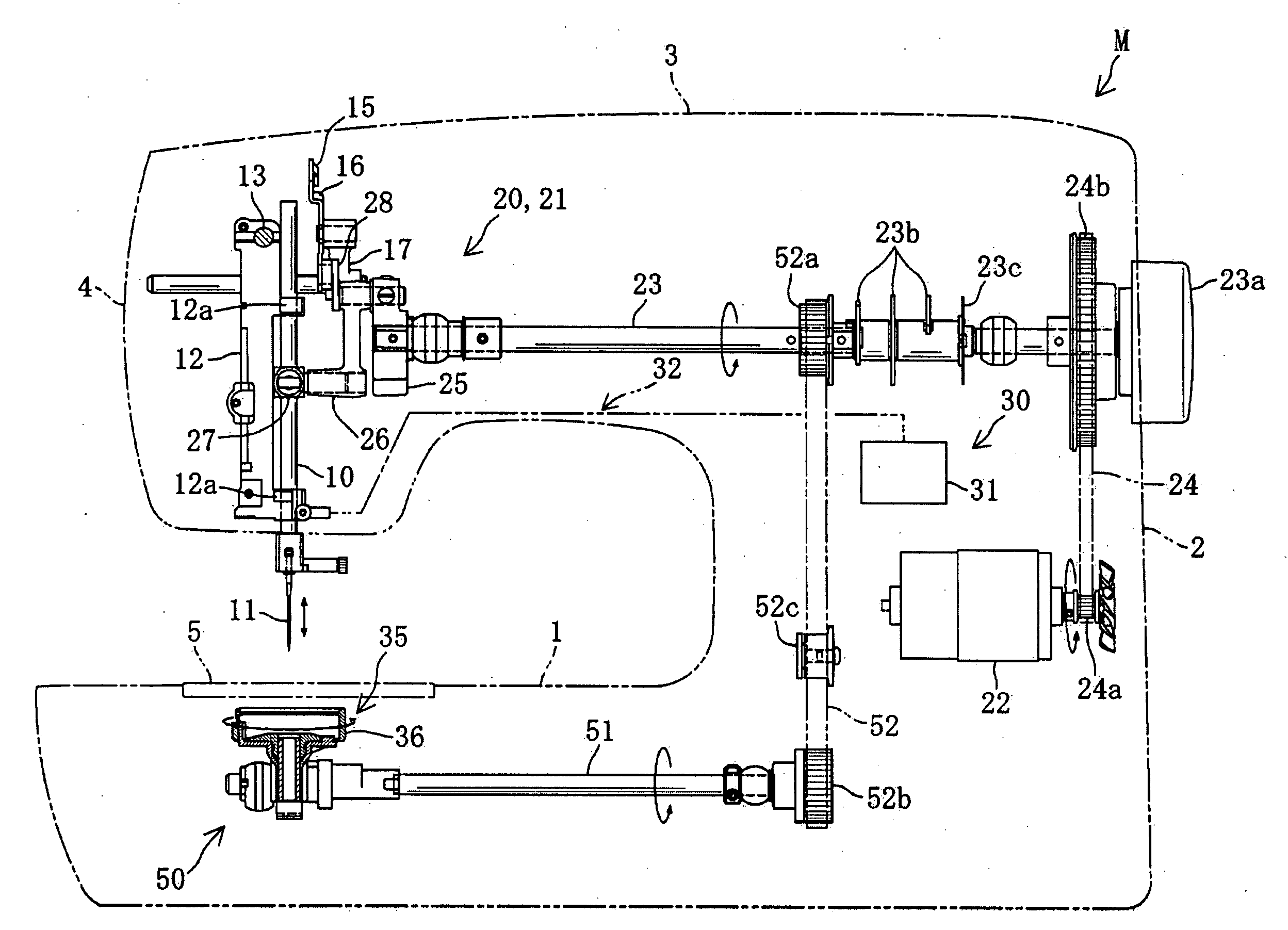
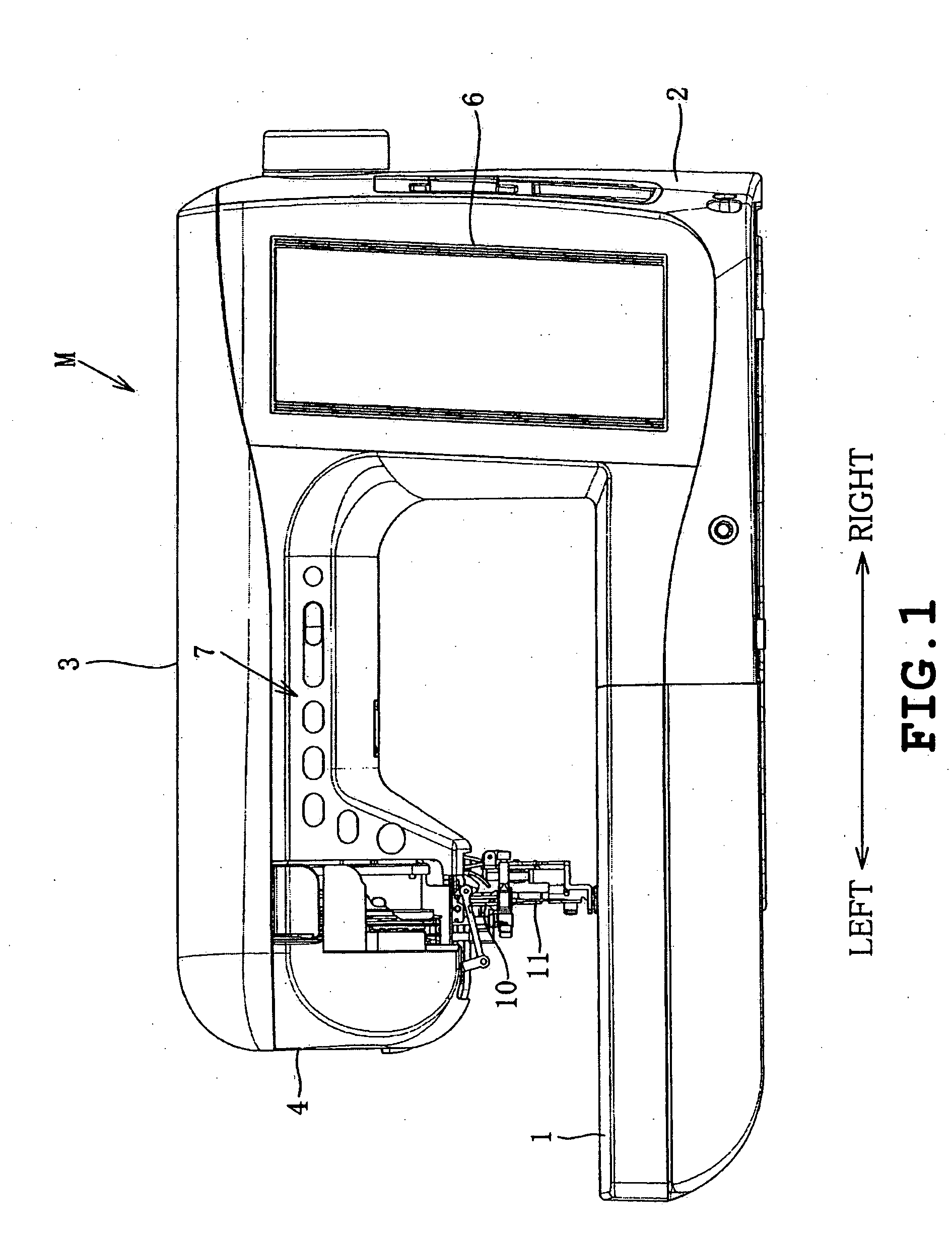
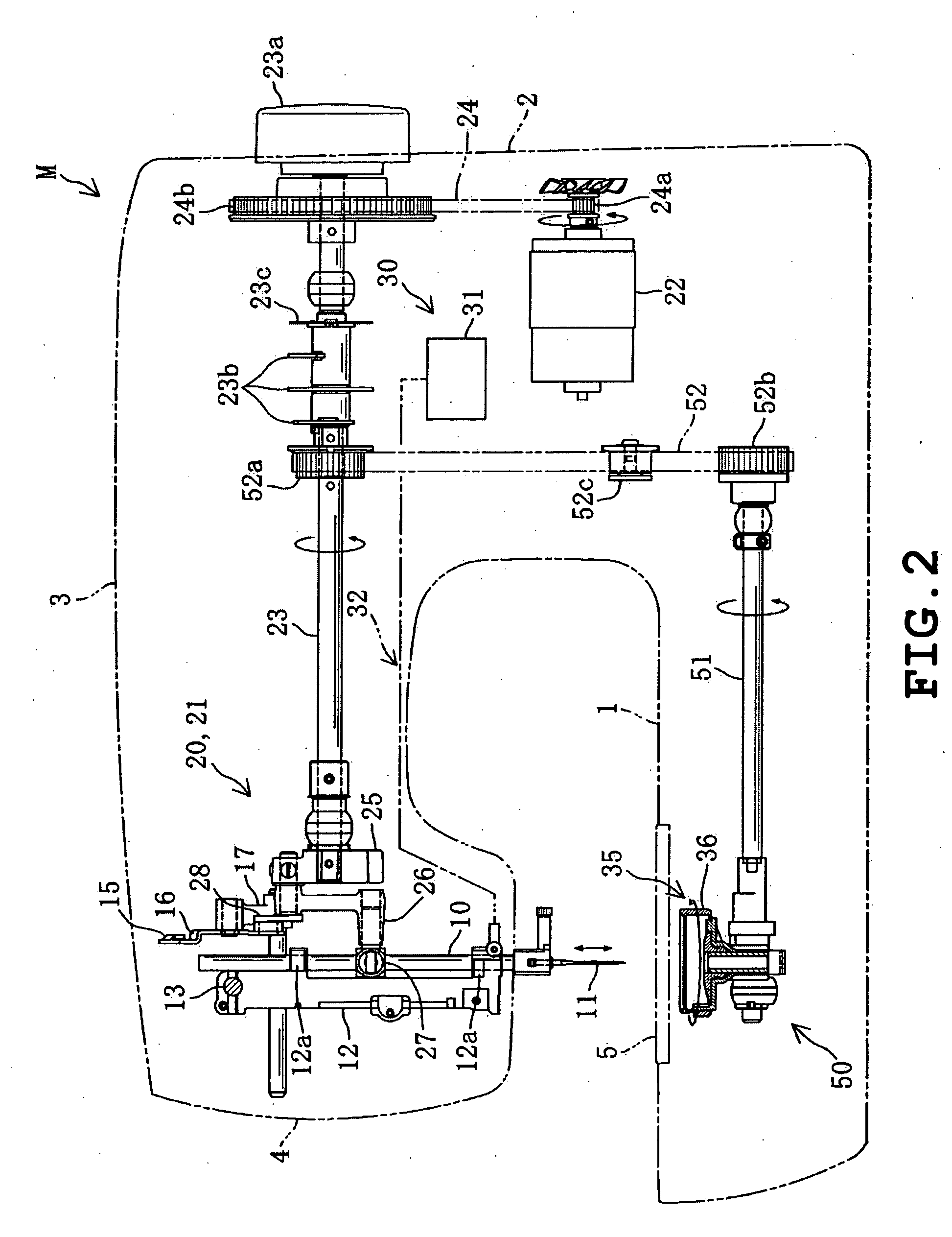
[0037]Referring now to FIGS. 1 and 2, a sewing machine M of the embodiment comprises a sewing bed 1, a pillar 2 and an arm 3. The pillar 2 is mounted on a right end of the bed 1. The arm 3 extends leftward from an upper portion of the pillar 2. A sewing head 4 is mounted on a left end of the arm 3. A needle plate 5 is mounted on an upper surface of the bed 1 opposed to the head 4. A liquid-crystal display 6 is mounted on a front of the pillar 2. Various operation switches 7 are provided on the fronts of the arm 3 and head 4. The sewing machine M further includes a needlebar 10, a sewing needle 11, a needle thread take-up 15, a needlebar vertical movement mechanism 20, a needle thread take-up swinging mechanism 21, a needle swinging mechanism 30, a horizontal rotating hook 35 and a hook driving mechanism 50.

[0038]The needlebar 10 is mounted on the head 4 so as to be reciprocable vertically and moveable horizontally as shown in FIG. 2. The needlebar 10 has a lower end protruding downw...

second embodiment

[0058]A second embodiment of the invention will be described. The sewing machine of the second embodiment further comprises a holding mechanism 64 and a cam operating unit. The holding mechanism 64 engages the engagement pin 63 with the cam groove 62 when zigzag stitches are formed. On the other hand, when no zigzag stitches are formed, for example, when straight stitches are formed only in synchronization with encounter of the hook beak with the needle thread loop in the case where the needle occupies the left needle location NL, the holding mechanism 64 holds the lower shaft gear 53 so that the lower shaft gear 53 is immovable axially relative to the lower shaft 51. The cam operating unit switches the cam mechanism 60 between a first and a second states. The cam mechanism 60 is operative and the holding mechanism 64 is inoperative in the inoperative state. In the second state, the cam mechanism 60 is inoperative and the holding mechanism 64 is operative.

[0059]Describing the constr...


PUM


Abstract

A sewing machine includes a rotating hook, a lower shaft rotating the rotating hook in synchronization with vertical movement of the needlebar, a lower shaft gear including a helical gear and slidably mounted on the lower shaft, a hook gear including a helical gear capable of mesh engagement with the lower shaft gear and mounted on the rotating hook, a drive force transmission mechanism supporting the lower shaft so that the lower shaft is axially moveable and transmits rotation of the lower shaft to the lower shaft gear, a cam mechanism axially moving the lower shaft gear to adjust at least one of a left encounter timing for seizure of the needle thread loop by the hook beak when the needle occupies a left needle location and a right encounter timing for seizure of the needle thread loop by the hook beak when the needle occupies a right needle location.

Description

CROSS-REFERENCE TO RELATED APPLICATIONS[0001]This application is based on and claims the benefit of priority from the prior Japanese Patent Application No. 2007-53744, filed on Mar. 5, 2007, the entire contents of which are incorporated herein by reference.BACKGROUND[0002]1. Field[0003]The present invention relates to a sewing machine having a needle swinging mechanism that swings a needle bar to a left needle location and a right needle location.[0004]2. Related Art[0005]Conventional lock stitch sewing machines capable of zigzag stitch comprise a needlebar, a needlebar vertical movement mechanism and a rotating hook. The needlebar has a lower end to which a sewing needle is attached. A needle has a needle eye through which a needle thread is insertable. The needlebar vertical movement mechanism moves the needlebar upward and downward. The rotating hook seizes a needle thread loop formed near to the needle eye.[0006]A type of sewing machine is provided with a needle swinging mechani...

Claims


Application Information

Patent Timeline
Patent Type & Authority Applications(United States)
IPC IPC(8): D05B69/02
CPCD05B3/02D05B69/02D05B55/14
Inventor YAMASAKI, HIROSHI
Owner BROTHER KOGYO KK
Why Eureka
Try Eureka