
Communicating Environmental Control System

Inactive Publication Date: 2008-09-11
RANCO OF DELAWARE
View PDF8 Cites 99 Cited by
  • Summary
  • Abstract
  • Description
  • Claims
  • Application Information

AI Technical Summary

Benefits of technology

[0008]In one aspect, an embodiment is an environmental control system for a building. The environmental control system includes a microprocessor controller configured for accepting at least two temperature set points and a humidity set point, an operating interface operably connected to the controller, a thermostat and at least one temperature sensor operably connected to the controller. The system also includes a humidistat and at least one humidity sensor operably connected to the co

Problems solved by technology

Significant amounts of energy, and thus energy costs, are required for the care and maintenance of vacant buildings or dwellings.
The cost of operating a heating and air-conditioning system, because of the cost of energy, tends to be much greater than the installed cost of the heating and air-conditioning system itself.
Thus, unoccupied “snow-bird” homes in the south may have their highest cooling costs in the summer, even though the homes are not occupied.
However, there are still significant energy costs, and the cooling system may fail.
If the cooling system fails, the building or home may incur damage because of high heat or high humidity, or from the consequences or high heat and humidity, such as mold and mildew damage.
Unoccupied homes and building in the north may have their highest heating costs in the winter, even though the homes are not occupied.
Owners may try to minimize their costs by setting the temperature set point low, but there are still very high heating costs.
If the heating system fails, the building or home may incur damage from burst pipes.

Method used


Image

  • Communicating Environmental Control System
  • Communicating Environmental Control System
  • Communicating Environmental Control System

Examples


Embodiment Construction

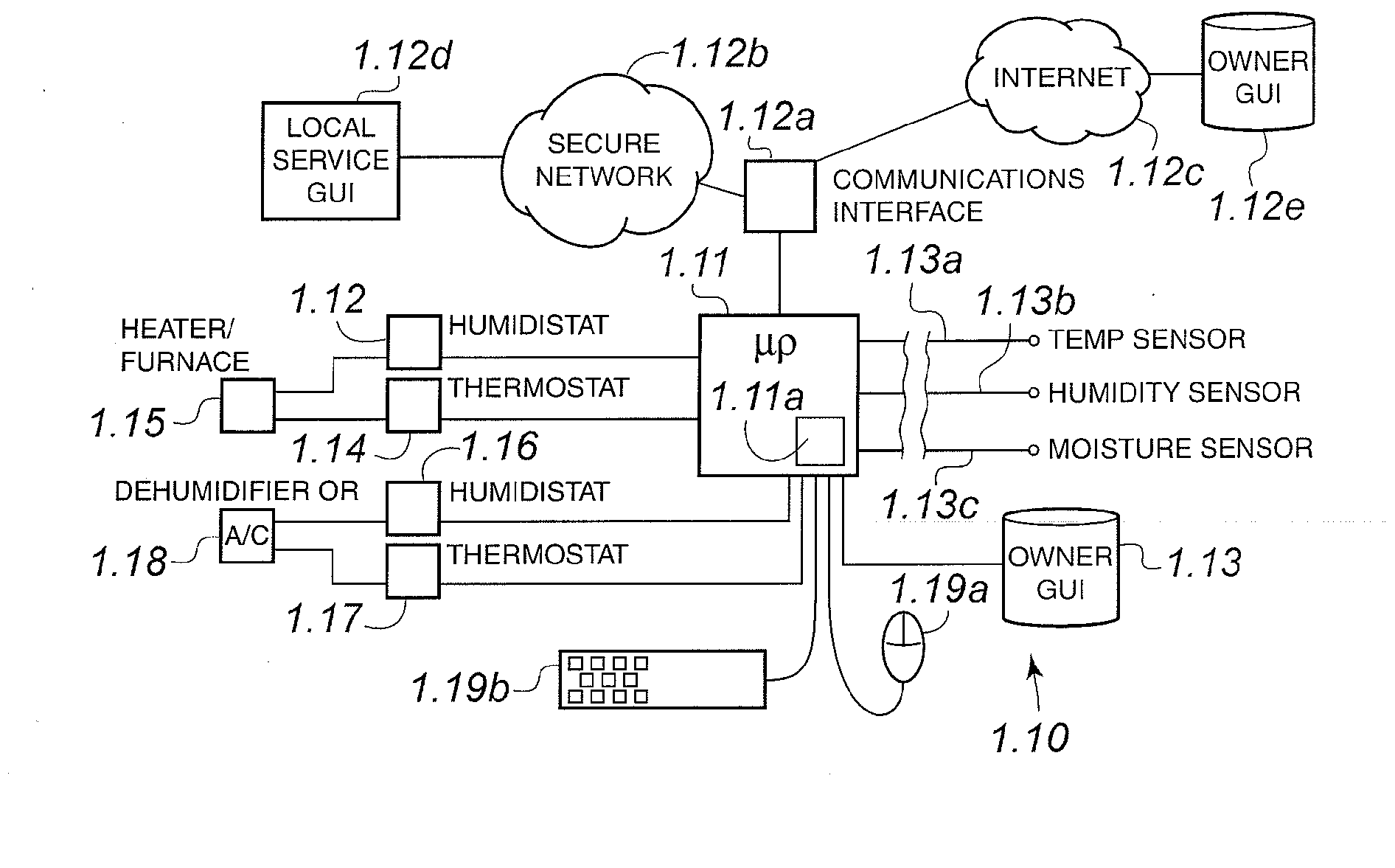
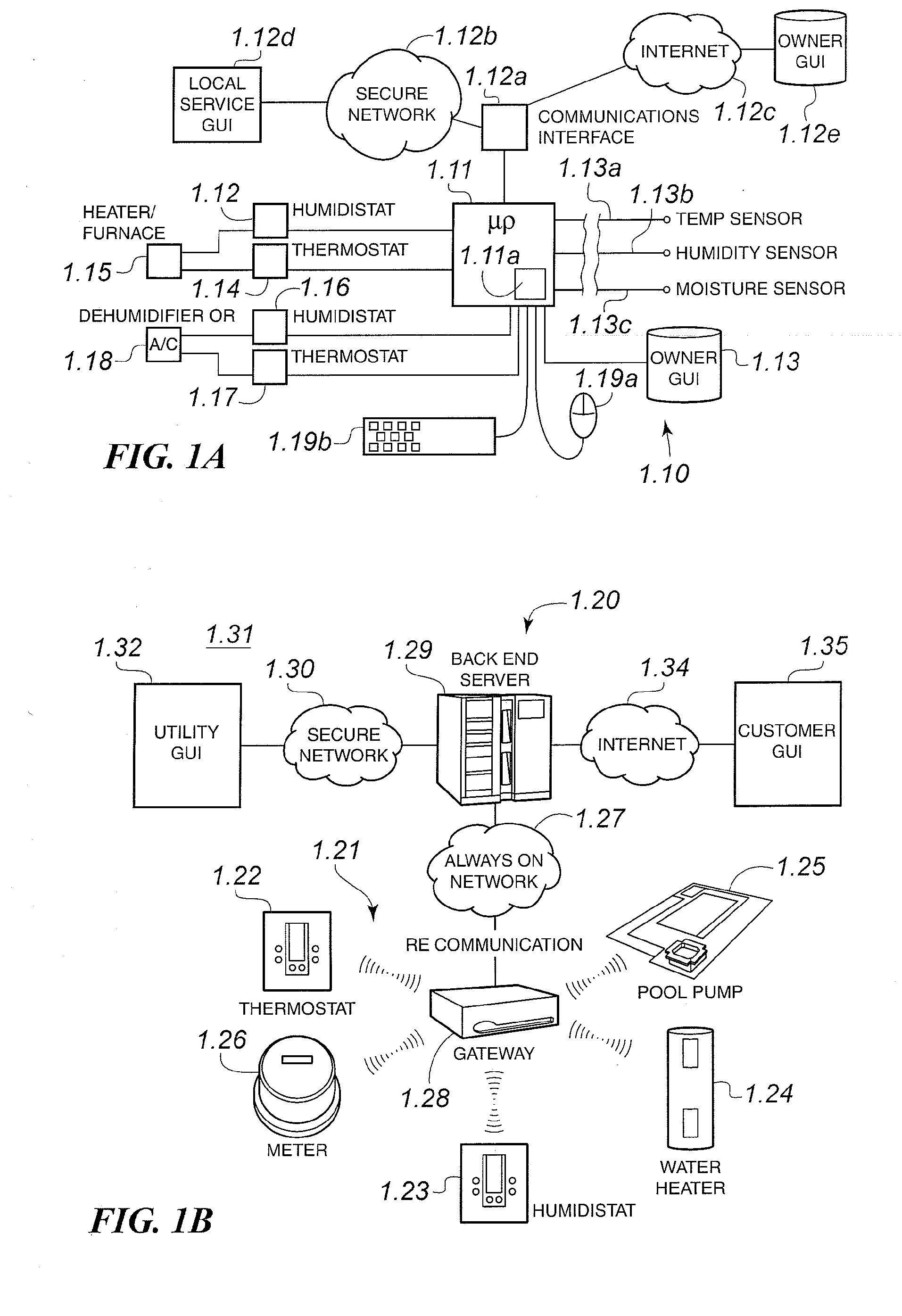
[0050]A first embodiment of an environmental control system according to the present invention is depicted in FIG. 1. In this embodiment, the control system 1.10 includes a central processing unit (CPU) such as a microprocessor 1.11 and a memory 1.11a. Microprocessor 1.12 preferably resides inside a house or other building and is used for controlling an environmental system for the house or building. The microprocessor is in communication with the outside world through communications interface or node 1.12a, which may be an Internet portal, an Ethernet connection, a USB connection, a telephone line, a radio antenna, or any other suitable equipment or combination for outside communications. Communications interface 1.12a may connect to a remote owner by the Internet 1.12c and the remote owner's local graphical user interface (GUI) 1.12e. The control system for the home or building may also connect to a local service provider or utility via the Internet or via a secure network 1.12b a...


PUM


Abstract

A communicating environmental control system for a dwelling or building is provided. The environmental control system is intended for use in a dwelling which may be unoccupied for a long period of time, e.g., months. The control system operates in an economy mode to prevent damage to the dwelling and its contents by avoiding condensation of moisture within the dwelling. At the same time, the control system minimizes operating costs by running more when energy costs are lower and running less when energy costs are higher. The control system switches to a comfort mode when the dwelling occupants return. The control system is in communication with a remote owner, a remote utility, or a remote service provider, or more than one of these, through the Internet or other communication system.

Description

FIELD OF THE INVENTION[0001]This invention generally relates to control of environmental conditions in a dwelling primarily by controlling humidity inside the dwelling and also by controlling a temperature of the dwelling.BACKGROUND OF THE INVENTION[0002]Control of energy costs is important as the price of all forms of energy continues to rise, and the supplies of energy, at least in the short run, tend to remain fixed. Significant amounts of energy, and thus energy costs, are required for the care and maintenance of vacant buildings or dwellings. Examples include buildings that are used seasonally. These include summer lodges or homes in northern climates which are used in one season, such as summer, and are vacant in the winter off-season. Other examples include homes in southern climates which are occupied in the winter. These homes are then vacant in the summer off-season, where the weather may include summer storms, hurricanes, and other high-humidity weather events.[0003]These...

Claims


Application Information

Patent Timeline
IPC IPC(8): F24F11/00
CPCG08B21/20
Inventor EHLERS, GREGORY ALLENBEAUDET, JOSEPH
Owner RANCO OF DELAWARE
Learn More