Automated meter reader

a meter reader and automatic technology, applied in the field of automatic meter reading, can solve the problems of inaccessibility of some meter, increased manual effort, and increased difficulty in maintenance, and achieve the effect of simple implementation, maintenance and repair

Active Publication Date: 2008-09-11
SENSUS SPECTRUM LLC
View PDF12 Cites 40 Cited by
  • Summary
  • Abstract
  • Description
  • Claims
  • Application Information

AI Technical Summary

Benefits of technology

[0011]Another object of the present invention is to provide a novel meter reader that does not require an extensive retrofitting process.
[0013]Yet another object of the present invention is to provide a novel wireless meter reader that can transmit metering information to a radio receiver, from which a utility company can gather and process the transmitted information.
[0014]Another object of the present invention is to provide a low-cost meter reader that is simple to implement, maintain and repair.

Problems solved by technology

This represents a significant expenditure of manual effort.
The situation is further exacerbated by the inaccessibility of some meters, e.g., located inside the basement of a house, and the unavailability for reading during normal working hours when the occupants of the house are not at home, but are at work.
This requires an extremely labor-intensive process of retrofitting the meters.
This retrofitting process also has a potential of damaging the meter.
This increases the battery consumption used by the meter reader and requires complicated circuitry.
In addition, the background devices only fit one particular type of meter and therefore several different types of meter readers are required.
Thus, the background meter reading devices are generally expensive to implement, maintain and repair.

Method used


Image

  • Automated meter reader
  • Automated meter reader
  • Automated meter reader

Examples


Embodiment Construction

[0042]Referring now to the drawings, wherein like reference numerals designate identical or corresponding parts throughout the several views, the present invention will be described.

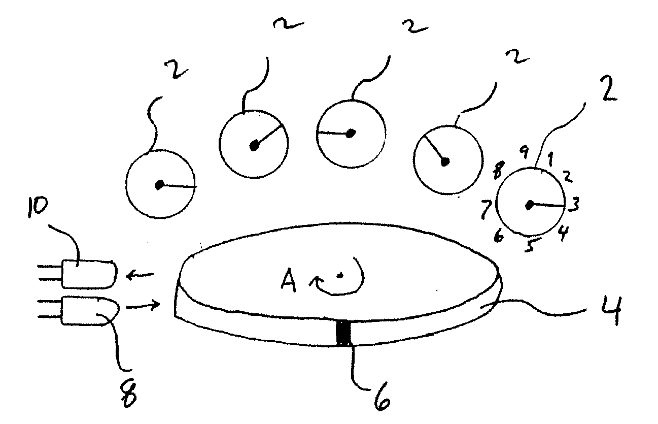
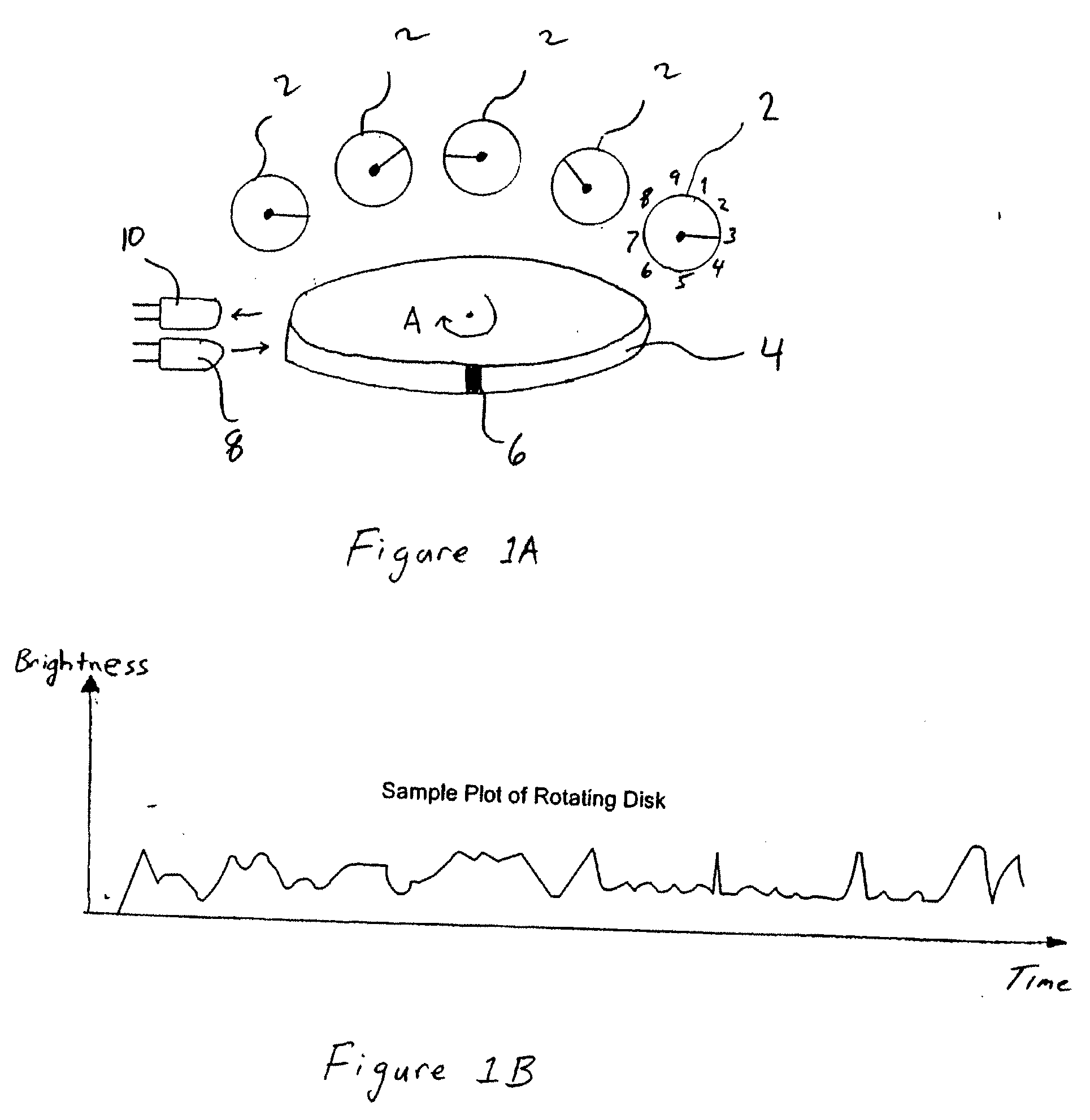
[0043]Turning first to FIG. 1A, this figure illustrates a first example of optically reading a meter according to the present invention. In this example, a meter reader according to the present invention includes a light emitter 8 and a light receiver 10. The light emitter 8 emits light towards a rotating disk 4 included in the electric meter. Light reflected from the rotating disk 4 is received by the light receiver 10. Note that in this example the user's current consumption (e.g., metering data) is determined from the rotating disk 4 and not the plurality of dials 2 accompanied with the meter. Also note the rotating disk 4 generally includes a single mark 6.

[0044]Thus, as the disk 4 rotates, the optical receiver 10 receives a varying amount of light. For example, FIG. 1B illustrates an example of diff...


PUM


Abstract

A meter reader for reading a meter have a display portion displaying a total output of a quantity being metered and plural incremental outputs defining the total output. The meter reader includes a sensing mechanism for sensing one of the plural incremental outputs in the meter display portion, and a processing unit coupled to the sensing mechanism for accumulating incremental outputs sensed by the sensing mechanism and for determining accumulated meter output over a time period based on the accumulated incremental outputs. Also included is an output mechanism for outputting the accumulated meter output determined by the processing unit. In one example, the sensing mechanism includes a sensor for sensing only a least significant incremental output in usage included in the meter display portion, and an emitter for illuminating the least significant incremental output included in the meter display portion. Further, the sensing mechanism senses the least significant incremental output included in the meter display portion at least once every full cycle of the least significant incremental output.

Description

BACKGROUND OF THE INVENTION[0001]1. Field of the Invention[0002]The present invention relates to automated meter reading, and more particularly to a meter reader including a sensor for sensing only a least significant incremental output in usage included in a meter display portion.[0003]2. Discussion of the Background[0004]Modem households are powered by electricity, gas and water, etc. The household receives electricity from the electrical company, in many cases a public utility. Similarly, natural gas is supplied by a gas provider, and water is supplied by the water commission.[0005]The consumption of electricity, gas and water is measured by meters which have been installed at the customer's house. For example, the electricity meter measures the amount of electricity (i.e., power) used by the household and the consumption of electric power is indicated by readings on the meter. The electrical meter typically includes a number of dials which show the power consumption in Kilowatt ...

Claims


Application Information

Patent Timeline
Patent Type & Authority Applications(United States)
IPC IPC(8): G08C15/06
CPCG01D4/008Y02B90/247Y02B90/24Y04S20/30Y04S20/50Y02B90/20
Inventor SANDERFORD, HUGH BRITTON
Owner SENSUS SPECTRUM LLC
Why Eureka
Try Eureka