Output level stabilization circuit and cml circuit using the same
- Summary
- Abstract
- Description
- Claims
- Application Information
AI Technical Summary
Benefits of technology
Problems solved by technology
Method used
Image
Examples
Embodiment Construction
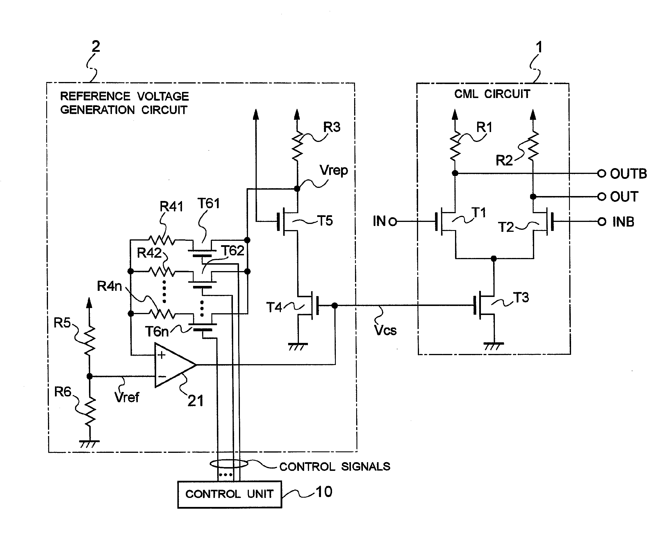
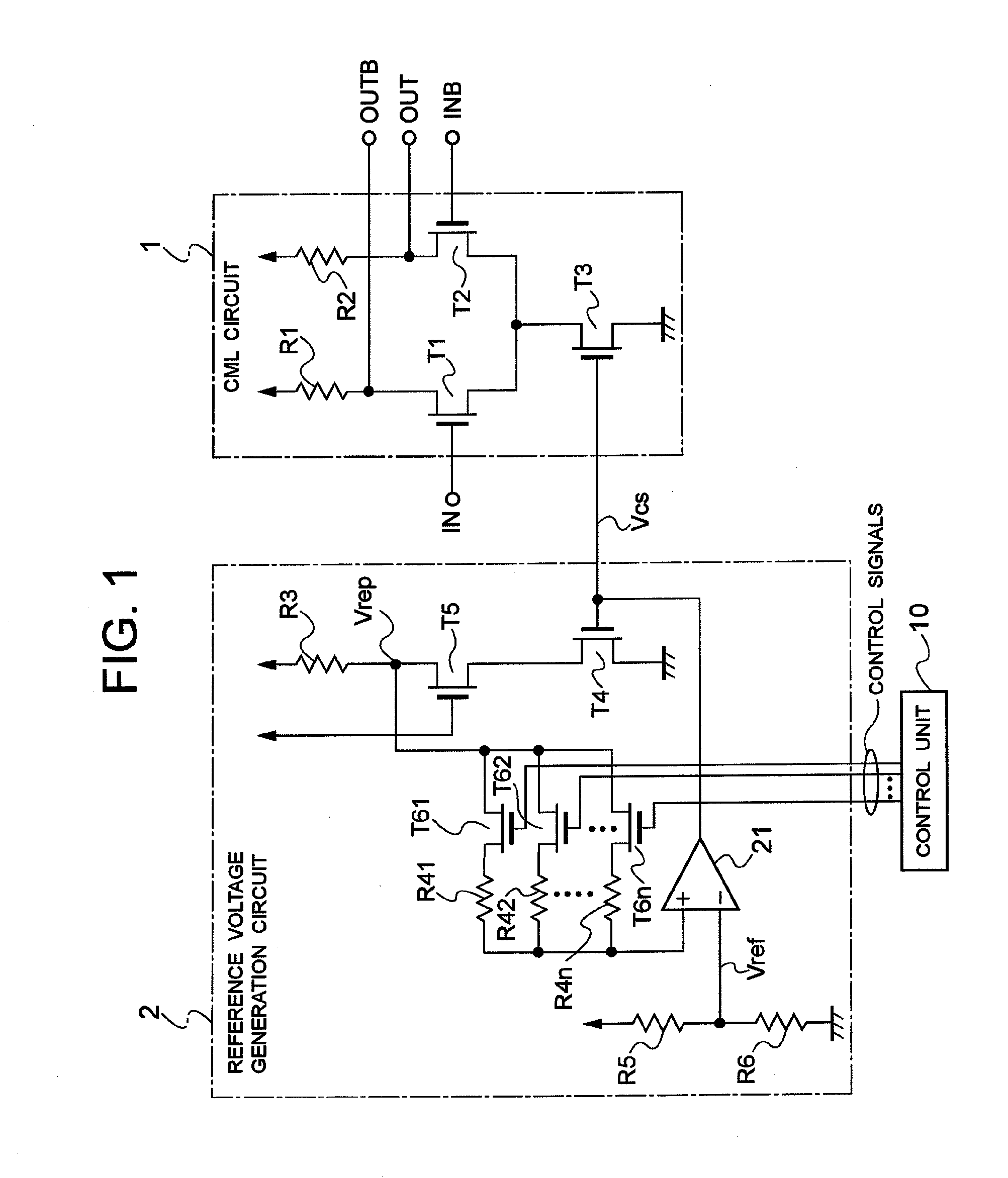
[0023]Exemplary embodiments of the invention will be described below with reference to the drawings. FIG. 1 is a circuit diagram according to an embodiment of the invention, in which the same reference characters are applied to parts corresponding to those of FIG. 4. Only parts different from FIG. 4 will be described with reference to FIG. 1. Referring to FIG. 1, multiple resistors R41 to R4n (n being an integer of two or more) are arranged in parallel, instead of the feedback resistor R4 in the feedback loop of FIG. 4.
[0024]In order to control insertion of these resistors R41 to R4n in the feedback loop, MOS transistors T61 to T6n are connected in series to the resistors R41 to R4n, respectively. Control signals are supplied to respective gates of the transistors T61 to T6n from a control unit 10, and using these control signals, the transistors T61 to T6n can be on-off controlled.
[0025]The other circuit constituent elements are identical to those of FIG. 4, and hence an explanatio...
PUM
 Abstract
Description
Claims
Application Information
 - R&D
- Intellectual Property
- Life Sciences
- Materials
- Tech Scout
- Unparalleled Data Quality
- Higher Quality Content
- 60% Fewer Hallucinations
Browse by: Latest US Patents, China's latest patents, Technical Efficacy Thesaurus, Application Domain, Technology Topic, Popular Technical Reports.
© 2025 PatSnap. All rights reserved.Legal|Privacy policy|Modern Slavery Act Transparency Statement|Sitemap|About US| Contact US: help@patsnap.com


