

Method and apparatus for distortion of audio signals and emulation of vacuum tube amplifiers
a technology of vacuum tube amplifiers and audio signals, applied in amplifier modifications, electrophonic musical instruments, instruments, etc., can solve the problems of loss of true non-linear dynamical behavior of tube amplifier stages, inability to fully capture the characteristics of non-linear distortion, and inability to fully emulate the effects of vacuum tube effects with software-based or digital tube modeling algorithms
- Summary
- Abstract
- Description
- Claims
- Application Information
AI Technical Summary
Benefits of technology
Problems solved by technology
Method used
Image

Examples
Embodiment Construction
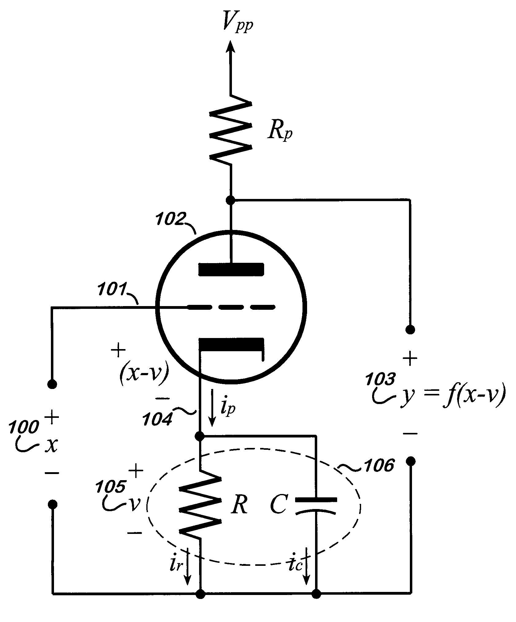
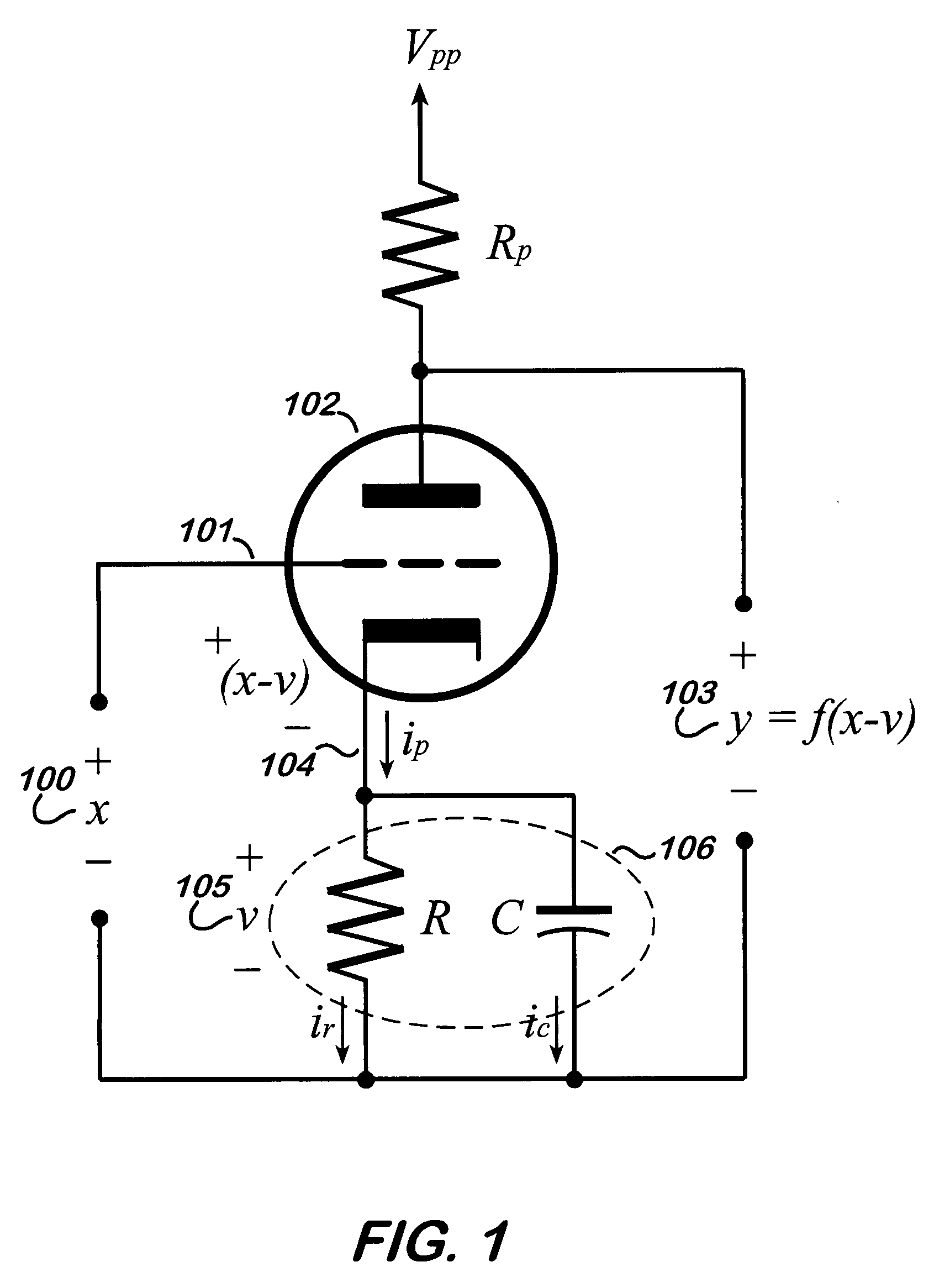
[0055]Referring to FIG. 1, a schematic of a tube amplifier stage is shown. An input signal 100 feeds the grid 101 of a vacuum tube 102 producing an output signal 103. The output signal 103 is dependent on the plate current of the tube, which is controlled by the voltage difference between the grid 101 and cathode 104. The voltage at the grid 101 is equivalent to the input signal 100, represented by x, and the voltage at the cathode 105 is represented by v. The output signal 103 is then proportional to a function of the difference, (x−v). This function, ƒ(x−v), as it is modeled by the present invention, is referred to as a transfer function. Additionally, the R-C network 106 found at the cathode 104 relates the plate current to the voltage at the cathode 105 which, in turn, affects the plate current. This recursive relationship of the output to the cathode voltage reveals a feedback phenomenon that occurs in tube amplifier stages and is important to the models of the present inventio...
PUM
 Abstract
Description
Claims
Application Information