Hand-Worn Signaling Device

a signaling device and hand-worn technology, applied in the direction of lighting support devices, instruments, lighting and heating apparatuses, etc., can solve the problems of unnecessarily slowing the flow of traffic, less effective at communicating traffic commands to drivers, and dangerous tasks

Inactive Publication Date: 2008-09-11
GALLOWAY KEVIN CHALGREN +1
View PDF11 Cites 39 Cited by
  • Summary
  • Abstract
  • Description
  • Claims
  • Application Information

AI Technical Summary

Benefits of technology

[0023]While many embodiments of the invention comprise a red light on the palm of the hand and a green light on the back of the hand, another embodiment comprises infrared lights on one or both sides of the hand. This enables the user to communicate in settings where other modes of communication would be impossible, such as military applications where a radio silence and low visibility must be maintained or underwater applications where a visible light would not be advisable. It should be noted that a digital camera, night-vision goggles and the like would be required to see the infrared light signals. Another embodiment of the invention can be used by airline persons to guide airplanes to airport gates; that embodiment comprises visible lights on both the palmar side and the dorsal side of the hand, of colors that are appropriate for that application.
[0024]All of the above-described embodiments of the invention can also comprise an interlock switch. One embodiment of the interlock switch is merely an on / off switch that can turn off the lights when the user is not actively directing traffic. Another embodiment of the interlock switch is a pushbutton or moment switch that must be kept pressed in order for the controller to respond to the hand motion, position or flexion. This prevents the user from inadvertently activating the wrong light.
[0025]When the user's hand is in proper signaling position, it is often difficult for the user to see whether the correct light-emitting assembly is turned on, as that surface of the hand is likely to be facing away from the user. To alleviate the problem, a feedback device is proposed. One embodiment of the feedback device comprises a light visible to the user when the appropriate light-emitting assembly is turned on. For example, the feedback light for the palmar light-emitting assembly could be located on the dorsal side of the hand, and vice versa. In that embodiment, when the palmar light-emitting assembly is turned on, the feedback light on the dorsal side of the user's hand is turned on; that feedback light is visible to the user. Similarly, when the dorsal light-emitting assembly is turned on, the feedback light on the palmar side of the user's hand is turned on and visible to the user. Another embodiment of the feedback device is a light that is located on the side of the user's hand in such a way that it is visible to the user regardless of the hand position. A further embodiment of the feedback device comprises a vibrating module that vibrates when a light-emitting assembly is turned on. This has the advantage of not requiring the user to look at the device, and can be programmed to vibrate in several different patterns to enable the user to detect which light-emitting assembly is on.

Problems solved by technology

In dark settings, this can be a very dangerous task.
Most traffic control personnel use flashlights or beacons to increase their visibility to oncoming traffic; however, while these devices are effective at improving visibility, they are less effective at communicating traffic commands to drivers.
Such tools can unnecessarily slow the flow of traffic by increasing driver confusion; moreover, they are heavy and preclude the use of the hand for other purposes.
Some designs, however, leave the control method altogether unspecified.
The pushbutton control method, while simple, has the disadvantage of requiring conscious action by the user, and of impeding the user's hand function.
While the Mead patent does disclose a light (attached to the glove with a hook-and-loop fastener), it does not disclose a method of turning that light on or off without removing it from the glove.
The Bain patent does not allow the user to manually operate the power switch with the glove hand, and has a singular light source mounted on the back of the hand.
However, because this network covers the entire length of each finger, it covers the fingertips and makes most normal uses of the hand impossible.
Such a device would not be useful to a traffic control officer, who needs to be able to use his or her hands for many other purposes during the course of a workday.
While this glove is useful for improving night-time visibility during the performance of some sports or other night-time activities, it will not be as useful for a traffic control officer, because, like the glove described in the Ferrari patent, it covers the fingertips.
Furthermore, the fiberoptic lights are only visible at the fingertips rather than at the back of the hand.
While this is a useful device for people who need such a glove for illumination, it is not ideal for traffic control officers because the brightest light is directed along the finger rather than outward from the front or back of the hand.
While this device is less cumbersome than the Ferrari patent, it still renders many normal uses of the hand impossible because it also covers the fingertips.
Furthermore, electroluminescent wire is not as bright as LED lights.
The Abas patent does not disclose how such a device should be controlled by the user.

Method used


Image

  • Hand-Worn Signaling Device
  • Hand-Worn Signaling Device
  • Hand-Worn Signaling Device

Examples


Embodiment Construction

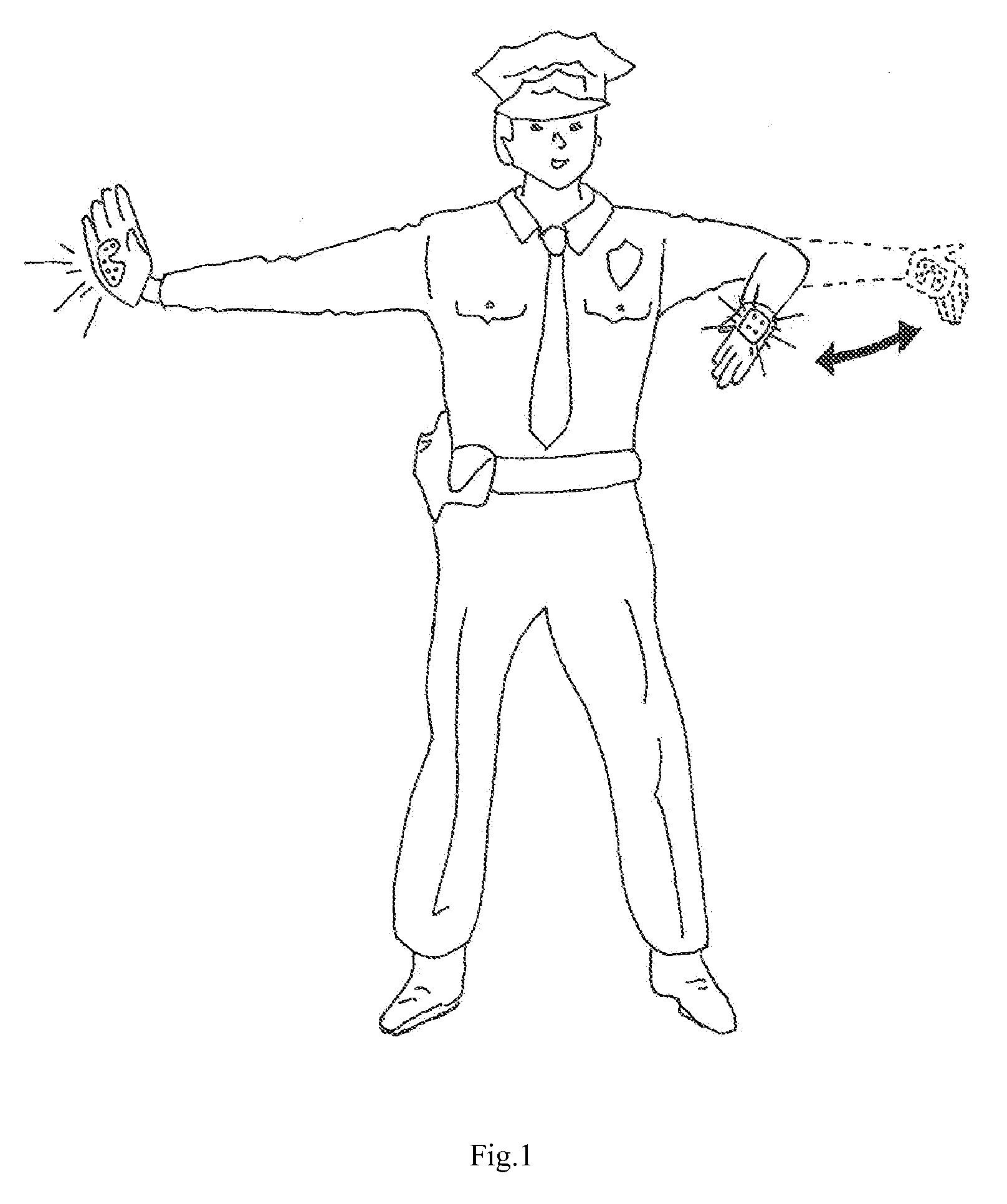
[0042]As illustrated in FIG. 1, when a traffic control officer makes a “stop” gesture, the palm of his or her hand is facing the person in front of him or her; when the officer makes a “move along” gesture, the back of his or her hand is facing the person in front of him or her. The present invention is a wearable device that will improve driver comprehension of these gestures by illuminating the hand surface visible to the driver with a red light when the officer makes a “stop” gesture and with a green light when the officer makes a “move along” gesture. Such an invention can also be used for guiding airplanes to the appropriate airport gate, military applications, or any other applications requiring communication with hand signals in dark environments.

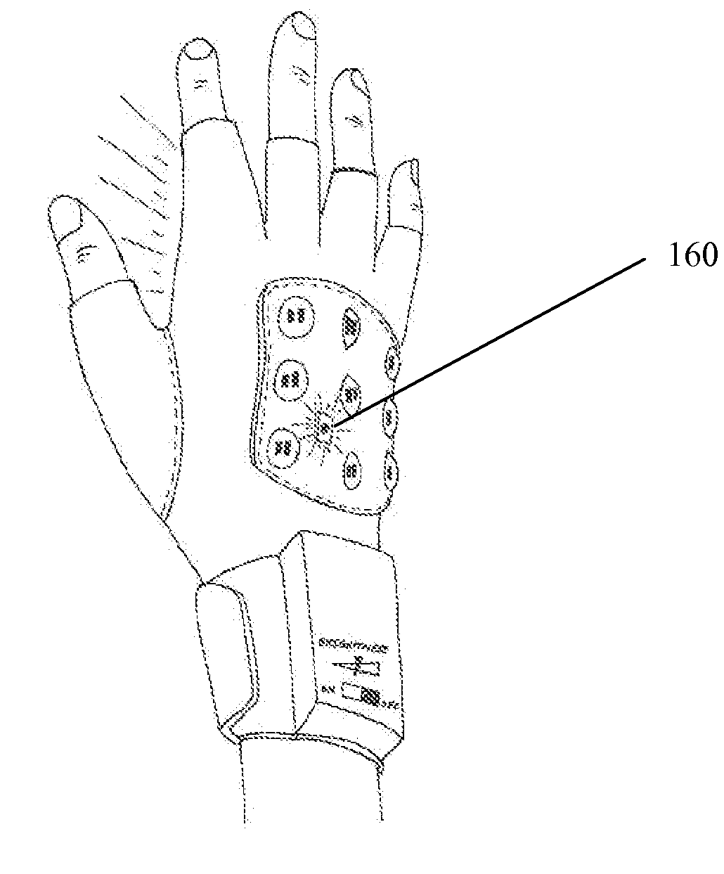
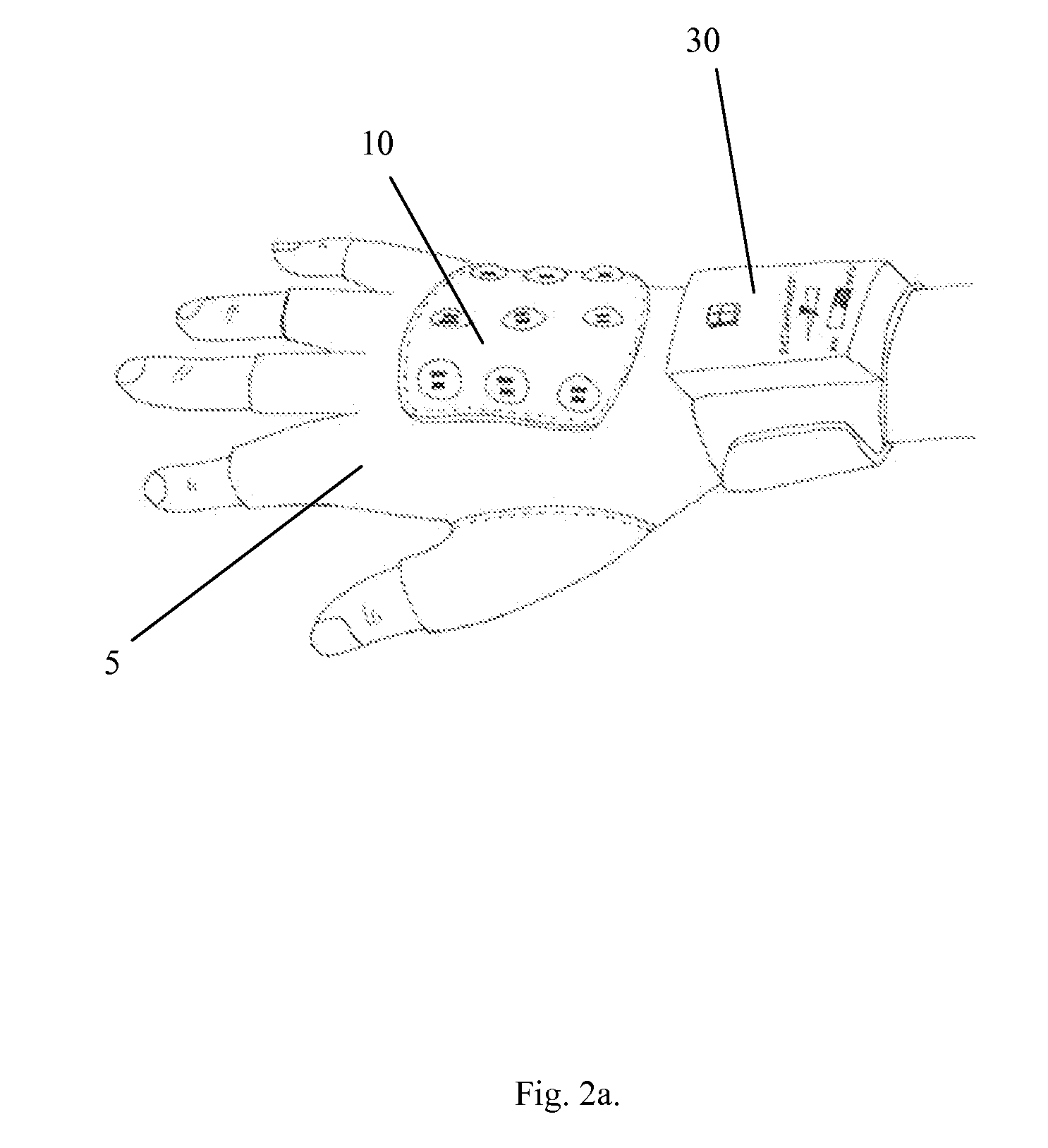
[0043]FIGS. 2(a) and 2(b) show the basic construction of one embodiment of the invention. The light-emitting assembly 10 (the “dorsal light-emitting assembly”) is located on the dorsal side of the hand and emits a green light when ac...


PUM


Abstract

An improved hand-worn signaling device is disclosed that comprises at least one light-emitting assembly on the palmar side of the hand and at least one light-emitting assembly on the dorsal side of the hand; in one embodiment of the invention, the palmar light-emitting assembly is red and the dorsal light-emitting assembly is green. One embodiment of the device also comprises a controller that detects hand motions by the user and activates the appropriate light-emitting assembly in response. In another embodiment, the controller detects the angle of the user's wrist or knuckles, and activates the appropriate light-emitting assembly depending on the angle of the user's joints. In another embodiment, the controller detects the spatial orientation of the user's hand, and activates the appropriate light-emitting assembly depending on whether the user's hand is positioned vertically with the fingers pointing straight up (the “stop” position) or in any other orientation. An interlock switch that prevents inadvertent activation, and a feedback device that enables the user to tell which light-emitting assembly is on, are also disclosed.

Description

CROSS-REFERENCE TO RELATED APPLICATIONS[0001]This application claims priority to Provisional Patent Application No. 60 / 905,666, filed on Mar. 08, 2007.STATEMENT REGARDING FEDERALLY SPONSORED RESEARCH OR DEVELOPMENT[0002]Not Applicable.THE NAMES OF THE PARTIES TO A JOINT RESEARCH AGREEMENT[0003]Not Applicable.INCORPORATION-BY-REFERENCE OF MATERIAL SUBMITTED ON A COMPACT DISC[0004]Not Applicable.BACKGROUND OF THE INVENTION[0005](1) Field of the Invention.[0006]This invention relates to warning or signaling devices, particularly to hand-worn warning or signaling devices used for controlling traffic.[0007](2) Description of Related Art.[0008]Traffic control personnel are frequently assigned to control traffic in situations where traffic lights are unavailable or inoperable. In dark settings, this can be a very dangerous task. Most traffic control personnel use flashlights or beacons to increase their visibility to oncoming traffic; however, while these devices are effective at improving...

Claims


Application Information

Patent Timeline
Patent Type & Authority Applications(United States)
IPC IPC(8): F21V21/08G05F1/00
CPCA41D19/0157H01H2203/0085G08B5/006F21V23/0492
Inventor GALLOWAY, KEVIN CHALGRENMATHER, THOMAS WILLIAM
Owner GALLOWAY KEVIN CHALGREN
Why Eureka
Try Eureka