Method for coupling two system components of a measuring device, in particular a coordinate measuring device

a technology of coordinate measuring and measuring device, which is applied in the direction of measurement device, electric/magnetic measuring arrangement, instruments, etc., can solve the problems of inability to carry out continuous radio transmissions with full bandwidth, inability to carry out continuous measurement, and inability to guarantee the accuracy of the measurement, so as to reduce the amount of inspection required, increase the security of emc, and save the effect of electrical transmission path

Active Publication Date: 2014-09-18
CARL ZEISS IND MESSTECHN GMBH
View PDF9 Cites 42 Cited by
  • Summary
  • Abstract
  • Description
  • Claims
  • Application Information

AI Technical Summary

Benefits of technology

[0059]As already mentioned above, it is thereby possible to save on an electrical transmission path. In this case, the corresponding ID chip of the respective system component, or the corresponding resistor, needs to be read out and the file needs to be provided to the light guide by means of corresponding coupling.
[0060]By transmission of the relevant data exclusively via an optical transmission path, it is possible to implement galvanic separation of this data transmission from the power supply on the electrical transmission path. In this way, the EMC security is increased and the necessary inspection outlay is reduced. Furthermore, separation of the electrical transmission paths into a network with a first voltage and a network with a second voltage makes it possible to avoid problems which may result from the sequence in which the electrical contacts are closed at the adapter interfaces. If one network or at least an equal ground reference is used, it may happen that temporary crosstalk from the power supply to the supply of the logic circuits may lead to damage in logic circuits in the system. The proposed separation avoids these problems.
[0061]As an alternative, it is possible for the driver module for the supply of the light guide cable not to be arranged until after the first adapter interface as seen from the sensor. In this way, the sensor can electrically transfer the digital data on a very short data path. This avoids the sensor transmitting into the light waveguide with the wrong wavelength. Furthermore, electrical contacts are typically more robust against dust and dirt in production environments. The sensor head is still exposed most strongly and directly to these conditions. For the data transmission in continuous rotation axes and in order to bridge the usually unavoidable adapter interfaces in coordinate measuring devices, in principle the same technology may be used. For a further refinement, a GRIN lens is placed before the end of the light guide fibers. The purpose of this lens is to collimate the light beam emerging divergently from the fiber. The adapter interfaces in the CMD are configured very robustly and reproducibly. In this way, the gap between the two parts of the interface, and also their relative position with respect to one another, are determined very well. A GRIN lens, which is used to couple the light into a subsequent further fiber, is in turn likewise arranged in the opposite part of the interface. By virtue of the parallel light beam in the gap, the gap can be bridged very simply and without great losses. In order to avoid losses when coupling the light in and out at the fiber ends and at the lens surfaces, these may correspondingly be optically bloomed. Typically, antireflection coatings are used or the fiber ends are cut slightly obliquely, or the fibers are positioned or a slight angle, in order to avoid influences due to single and multiple reflections.

Problems solved by technology

This, however, is too low for data transmission of modern camera systems, since an image size of one megapixel and a resolution of 8 bits per image incurs 1 MB of data.
Furthermore, radio transmissions usually cannot be carried out continuously with full bandwidth, which makes continuous measurement even more difficult, or even prevents it.
With known technologies, consequently, efficient transmission of large image data quantities is scarcely possible.
However, since only tactile sensors are used in this case, the data rates are much lower.
The problem for the coordinate measuring devices thus arises specifically when the sensor used is suitable for fast measurements and therefore also high data rates.
This problem hence occurs particularly in the case of fast-scanning or optical sensors.
To date, however, the prior art has lacked interface arrangements which permit flexible arrangement of both tactilely and optically measuring sensor heads in coordinate measuring devices with effective energy transmission and high data transmission rates.

Method used


Image

  • Method for coupling two system components of a measuring device, in particular a coordinate measuring device
  • Method for coupling two system components of a measuring device, in particular a coordinate measuring device
  • Method for coupling two system components of a measuring device, in particular a coordinate measuring device

Examples


Embodiment Construction

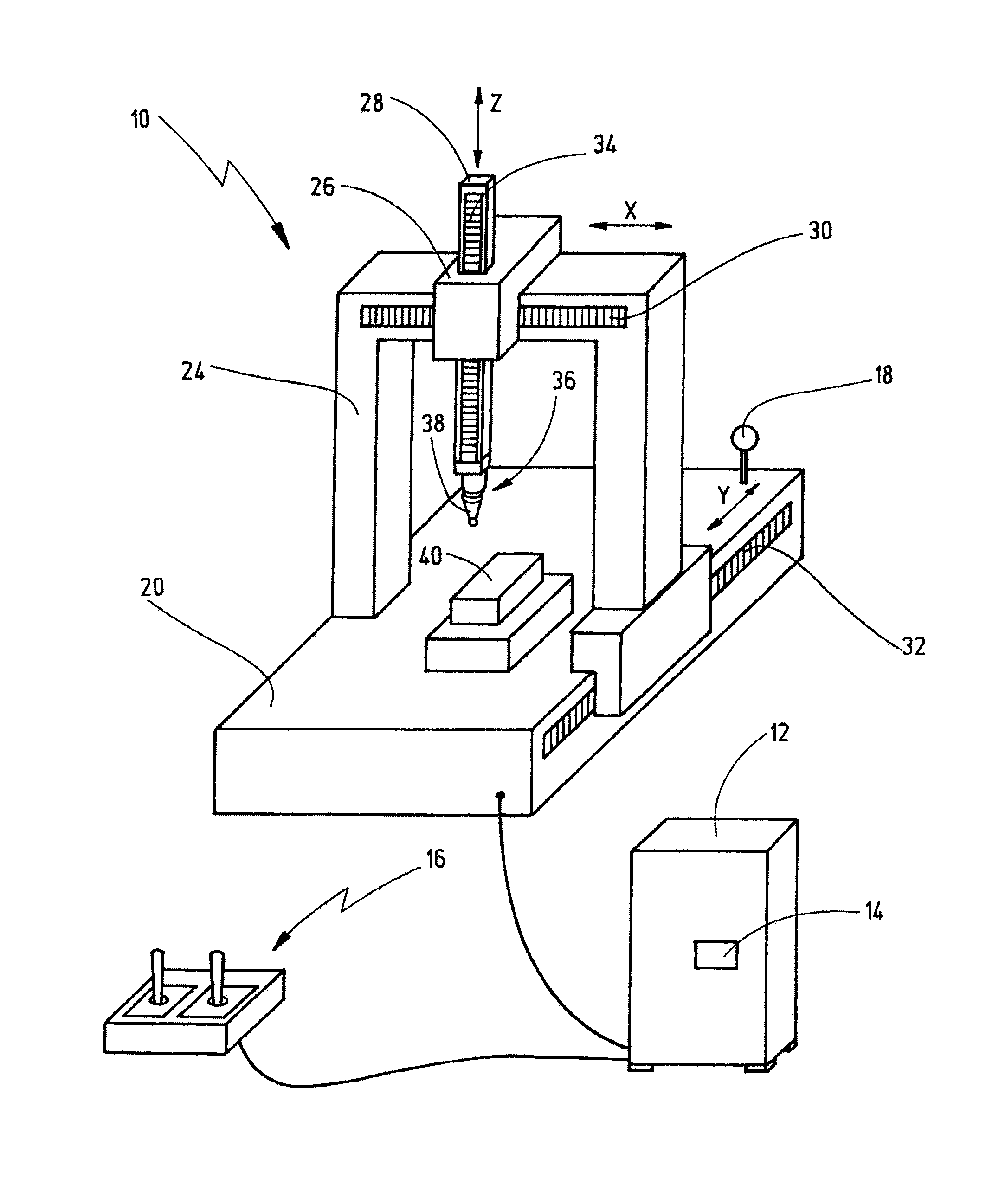
[0082]FIG. 1 shows a measuring device, which is formed as coordinate measuring device 10. In principle, the measuring device may also be a part of a machine tool or manufacturing machine. The invention will, however, be described below with reference to the example of a coordinate measuring device 10.

[0083]The coordinate measuring device 10 comprises a control unit 12 for controlling the coordinate measuring device 10. The control unit 12 comprises a computation unit 14, for example a computer.

[0084]The control unit 12 is represented merely schematically as a block, although in principle the control unit 12 may comprise all elements necessary for controlling the coordinate measuring device 10, for example keypads, monitors or a control panel 16. Furthermore, the control unit 12 also comprises an output means in order to output the data obtained by the coordinate measuring device 10 in a suitable form, for example electronically or in paper form. Although the coordinate measuring dev...


PUM


Abstract

A method for coupling a first system component and a second system component of a coordinate measuring device for determining by means of at least one sensor the three-dimensional coordinates of an object to be measured. An interface arrangement is provided between the first system component and the second system component. The interface arrangement comprises an electrical interface, formed from at least two electrical transmission paths, for transmitting a first electrical voltage between the first system component and the second system component, and at least one optical interface formed from light waveguides. The at least one sensor is supplied with the first electrical voltage via the two electrical transmission paths of the electrical interface. An analog measurement signal from the sensor is converted into a digital measurement signal. The digital measurement signal is transmitted by means of the light waveguides of the optical interface.

Description

CROSS-REFERENCE TO RELATED APPLICATIONS[0001]This is a Continuation application of International patent application PCT / EP2011 / 073700, filed Dec. 21, 2011. The entire contents of this prior application is incorporated herein by reference.BACKGROUND OF THE INVENTION[0002]The present invention relates to a method for coupling a first system component and a second system component of a measuring device, in particular a coordinate measuring device, for determining by means of a sensor a property, in particular three-dimensional coordinates and / or other specific local properties, for example roughness, color or scattering behavior, of an object to be measured, wherein an interface arrangement is provided between the first system component and the second system component, wherein the interface arrangement is provided with at least one electrical interface, formed from at least two electrical transmission paths, for transmitting a first electrical voltage between the first system component...

Claims


Application Information

Patent Timeline
Patent Type & Authority Applications(United States)
IPC IPC(8): G01B5/008
CPCG01B5/008G01B11/007G01B7/008G01B11/005
Inventor ENGEL, THOMAS
Owner CARL ZEISS IND MESSTECHN GMBH
Why Eureka
Try Eureka