Fiber optic connector with double-clad stub fiber

a fiber optic connector and fiber optic technology, applied in the field of fiber optic connectors, can solve the problems of optical interference effects, overall increase in the loss of insertion of the connector interface,

Inactive Publication Date: 2008-09-11
PANDUIT
View PDF24 Cites 34 Cited by
  • Summary
  • Abstract
  • Description
  • Claims
  • Application Information

AI Technical Summary

Benefits of technology

[0005]A field-terminated pre-polished fiber optic connector assembly for terminating a single-clad optical field fiber includes a double-clad optical stub fiber and an alignment member. The alignment member receives the cleaved end of the field-terminated optical field fiber, which abuts against an end of the double-clad optical stub fiber forming an interface at the point of abutment. The double-clad optical stub fiber includes a core having a radius rc, an inner cladding having a radius r1, and an outer cladding having a radius r2. The ratio r1:rc is less than 6.5:1. The refractive index of the inner cladding is down-doped to result in an effective refractive index that is at least 0.0025 lower than that of the core but higher than that of the outer cladding's refractive index. The mode field diameter (MFD) of the double-clad optical stub fiber approximately matches the MFD of the field fiber. In one implementation, the optical field fiber and double-clad optical stub fiber are of the single-mode type. In another implementation, the optical field fiber and double-clad optical stub fiber are of the multimode type. The optical field fiber can also be a double-clad fiber.

Problems solved by technology

But in reality, optical interference effects occur as a result of misalignment of the cores of the field and stub fibers or mismatch of the mode-field diameter (MFD) or optical-power distribution for the field and stub fibers.
This interference can be constructive or destructive, which, in the latter case, causes an overall increase in insertion loss of the connector interface.

Method used


Image

  • Fiber optic connector with double-clad stub fiber
  • Fiber optic connector with double-clad stub fiber
  • Fiber optic connector with double-clad stub fiber

Examples


Embodiment Construction

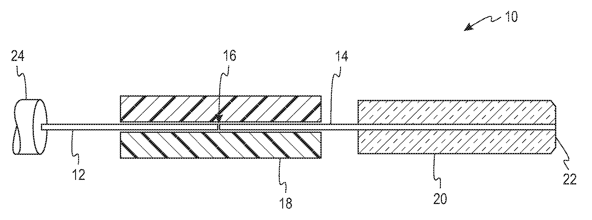
[0009]FIG. 1 is a cross-sectional side illustration of a field-terminated pre-polished fiber optic connector 10 for terminating a field fiber 12, according to an aspect of the present invention. The field fiber 12 is a single-mode optical fiber having a single cladding. The connector 10 couples together the field fiber 12 with a stub fiber 14, which forms an interface 16 where the two fibers 12, 14 abut against one another within the connector 10. The connector 10 is optionally of the type generally described in commonly assigned, U.S. Pat. No. 7,011,454, entitled “Reversible Fiber Optic Stub Fiber Connector,” issued Mar. 14, 2006, though other fiber optic connectors can be used. An alignment member 18 may comprise v-groove planks for aligning ends of the fibers 12, 14 in a fixed relationship with one another. A ferrule 20 surrounds part of the stub fiber 14, and a pre-polished end of the stub fiber 14 is positioned at a pre-polished front face 22 of the ferrule 20 so that together ...


PUM


Abstract

A fiber optic connector having a double-clad specialty optical stub fiber with a deep index core-to-inner-cladding profile and a raised index outer-cladding profile. The double-clad optical stub fiber abuts against a single-clad field optical fiber of the single-mode type to form an interface across which the primary mode traverses without significantly interfering with higher-order modes. The ratio of the radius of the inner cladding to the radius of the core of the stub fiber is less than 6.5:1. The index profile of the refractive index of the inner cladding is deep relative to the refractive index of the core to confine the primary mode within the core. The raised refractive index of the outer-cladding pulls the higher-order modes deeper into that region, reducing interference with the primary mode. The respective core diameters of the field and stub fibers are matched to avoid mode-field diameter mismatch.

Description

FIELD OF THE INVENTION[0001]The present invention relates generally to fiber optic connectors, and, more particularly, to a field-terminated, pre-polished fiber optic connector having a double-clad stub fiber for minimizing optical interference effects caused by excitation of higher-order modes.BACKGROUND OF THE INVENTION[0002]Field-terminated pre-polished fiber optic connectors include an interface at which two optical fibers, a field optical fiber (“field fiber”) and an internal stub optical fiber (“stub fiber”), are coupled. Such connectors include a pre-polished front face that enables a connection with another compatible fiber optic connector. In such a connector, the stub fiber is essentially disposed between two interfaces: the field fiber-stub fiber interface, and the connector interface with the compatible connector at the pre-polished front face.[0003]Ideally, all of the light energy passing through the core of a single-mode field fiber will continue unimpeded across the i...

Claims


Application Information

Patent Timeline
Patent Type & Authority Applications(United States)
IPC IPC(8): G02B6/38G02B6/36
CPCG02B6/03627G02B6/3846G02B6/3806G02B6/36G02B6/38
Inventor PIMPINELLA, RICHARD J.BRUNSTING, ALBERT
Owner PANDUIT
Why Eureka
Try Eureka