Image forming apparatus, process cartridge, and image forming method

Inactive Publication Date: 2008-09-11
RICOH KK
View PDF22 Cites 13 Cited by
  • Summary
  • Abstract
  • Description
  • Claims
  • Application Information

AI Technical Summary

Benefits of technology

[0014]Embodiments of the present invention provide an image forming apparatus, a process cartridge, and an image for

Problems solved by technology

One disadvantage of a tandem electrophotographic method is that it complicates the structure of an imaging engine and increases the size and cost of the imaging engine due to its use of multiple photoconductors.
However, the configura

Method used


Image

  • Image forming apparatus, process cartridge, and image forming method
  • Image forming apparatus, process cartridge, and image forming method
  • Image forming apparatus, process cartridge, and image forming method

Examples


Example

First Embodiment

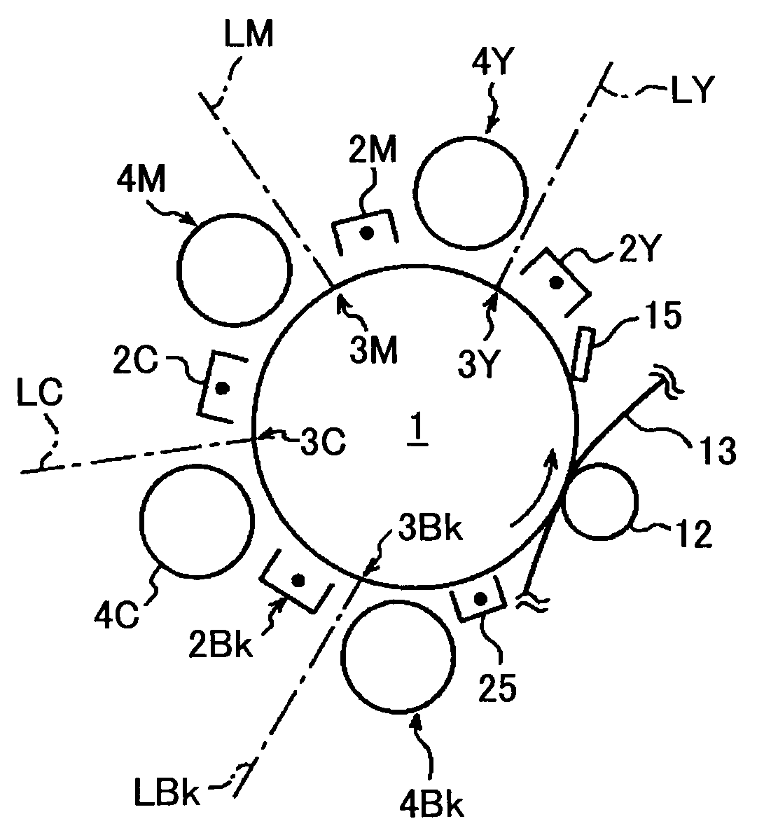
[0060]FIG. 3 is a schematic diagram of an imaging unit according to a first embodiment of the present invention. In this embodiment, the photoconductive drum 1 is positively-chargeable and has a photoconductive layer with a thickness of about 20 μm. The charging units 2Y, 2M, 2C, and 2Bk are implemented by direct-current (DC) scorotron chargers. Each of the exposing components 3Y, 3M, 3C, and 3Bk of the exposing unit 5 emits a laser beam L with a near-infrared wavelength of 780 nm that easily penetrates a toner layer. Basically, a laser beam having any wavelength greater than that of near-infrared rays may be used as the laser beam L. The developing units 4Y, 4M, 4C, and 4Bk develop without contact (with a developing gap of 150 μm) latent images by a one-component DC jumping development method. In the image-on-image development method, a toner image of a subsequent color is formed on a toner image of a preceding color. Therefore, in the image-on-image development me...

Example

Second Embodiment

[0070]In a second embodiment of the present invention, a developing unit shown in FIG. 4 is used as each of the developing units 4Y, 4M, 4C, and 4Bk. As are the developing units 4 of the first embodiment, the developing units 4 of the second embodiment are noncontact developing units that do not disturb preceding toner images.

[0071]The developing units 4 of the second embodiment are described below in detail.

[0072]As shown in FIG. 4, the developing unit 4 of this embodiment includes a toner carrying roller 61, a mag roller 62, agitating screws 63 and 64, and a case containing the agitating screws 63 and 64 and two-component developer. Except for the toner carrying roller 61, the developing unit 4 has a configuration similar to that of a normal two-component developing unit. The two-component developer comprises magnetic carrier particles with a particle diameter of about 50 μm and toner with a particle diameter of about 6 μm. The weight percentage of toner in the t...

Example

Third Embodiment

[0080]FIG. 9 is a schematic diagram of the developing unit 4 according to a third embodiment of the present invention. The developing unit 4 of the third embodiment has a configuration similar to that of the second embodiment. The developing unit 4 of the third embodiment is different from that of the second embodiment in that a toner carrying roller 68, which is not rotated, is provided instead of the toner carrying roller 61. In the toner carrying roller 68, the electrodes 66 are arranged at intervals and categorized into three groups (Va2-applied electrodes, Vb2-applied electrodes, and Vc2-applied electrodes) as shown in FIG. 10, and voltages Va2, Vb2, and Vc2 with different waveforms as shown in FIG. 12 are applied to the respective groups as shown in FIG. 11. As in the second embodiment, toner on the toner carrying roller 68 hops between the Va2-applied electrode and the Vb2-applied electrode and between the Vb2-applied electrode and the Vc2-applied electrode, a...


PUM


Abstract

A disclosed image forming apparatus includes an image carrier; one or more charging units configured to charge the image carrier in preparation for formation of each of plural latent images corresponding to toner images of different colors; a latent image forming unit configured to expose non-image areas on the charged image carrier to form each of the latent images; and developing units configured to develop the corresponding latent images in sequence with toners of the corresponding colors to form the toner images and thereby to form a color toner image composed of the toner images of the different colors on the image carrier, the toners having polarity opposite to that of the charged image carrier.

Description

BACKGROUND OF THE INVENTION[0001]1. Field of the Invention[0002]The present invention generally relates to an image forming apparatus such as a copier, a fax machine, and a printer, a process cartridge attachable / detachable to / from the image forming apparatus, and an image forming method. More particularly, the present invention relates to an image forming apparatus, a process cartridge, and an image forming method for forming a multicolor image by superposing toner images of different colors on one image carrier.[0003]2. Description of the Related Art[0004]Tandem electrophotographic methods, which employ multiple photoconductors, are widely used for high-speed color printing. One disadvantage of a tandem electrophotographic method is that it complicates the structure of an imaging engine and increases the size and cost of the imaging engine due to its use of multiple photoconductors. To eliminate or lesson this problem, an image-on-image development method has been proposed. In the...

Claims


Application Information

Patent Timeline
IPC IPC(8): G03G15/02G03G13/06
CPCG03G15/0126G03G15/0163G03G2215/017G03G15/0152
Inventor TSUKAMOTO, TAKEOAOKI, KATSUHIROYASUTOMI, KEIMARUYAMA, HITOSHISAITOH, MASANORIMIYAWAKI, KATSUAKI
Owner RICOH KK
Why Eureka
Try Eureka