Cutting insert

Inactive Publication Date: 2008-09-11
MITSUBISHI MATERIALS CORP
View PDF5 Cites 32 Cited by
  • Summary
  • Abstract
  • Description
  • Claims
  • Application Information

AI Technical Summary

Benefits of technology

[0026]According to the present invention as described above, it is possible to reliably dispose of cutting chips in the finish cutting for cutting small amount. In addition, it is also possible to provide a cutt

Problems solved by technology

Thus, it is difficult to form the aforementioned standing angle since a gradient of the standing face is steep based on a protrusion height of the top portion of the protrusion and a distance from the top portion to the cutting edge.
Accordingly, in the mediu

Method used


Image

  • Cutting insert
  • Cutting insert
  • Cutting insert

Examples


Embodiment Construction

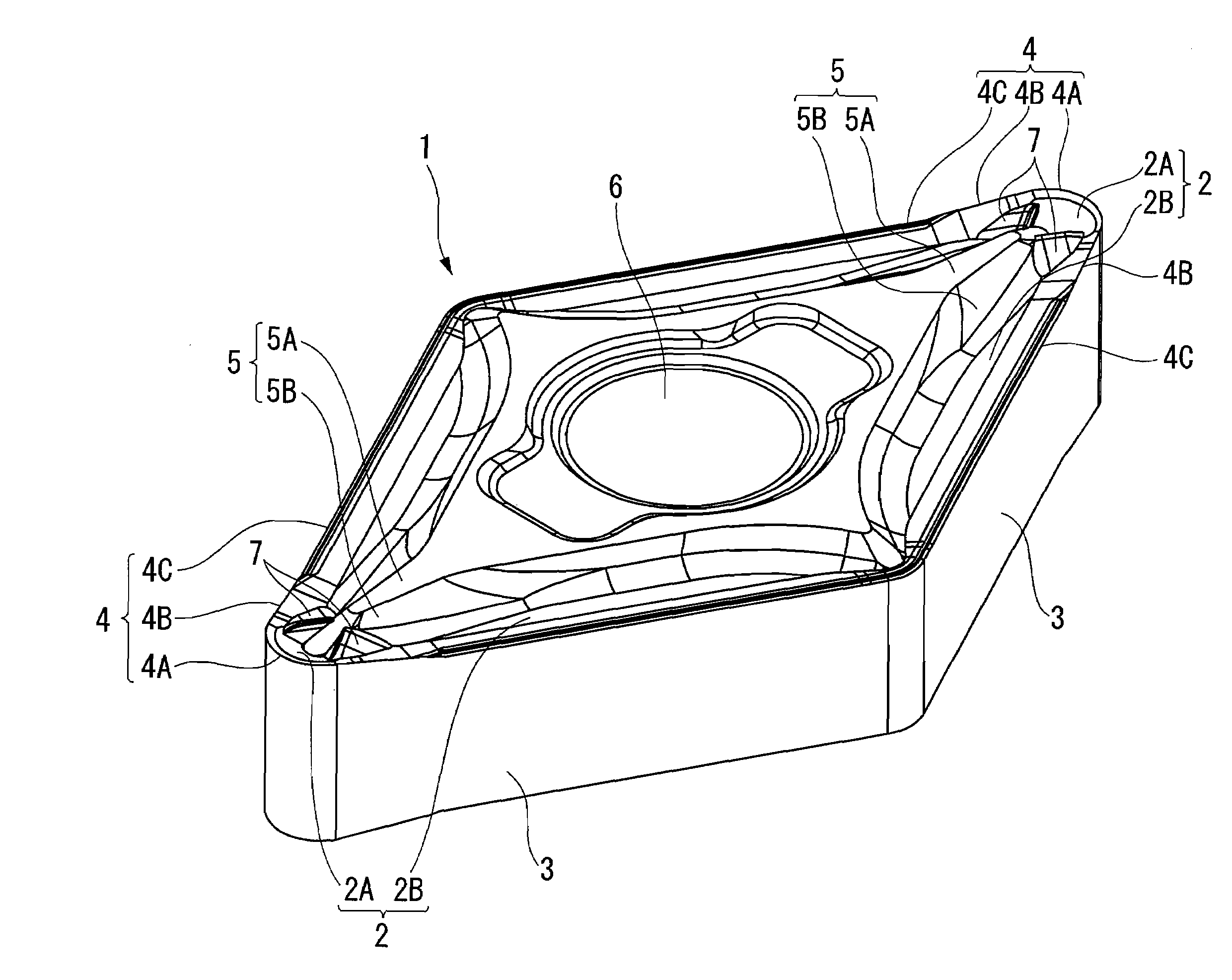
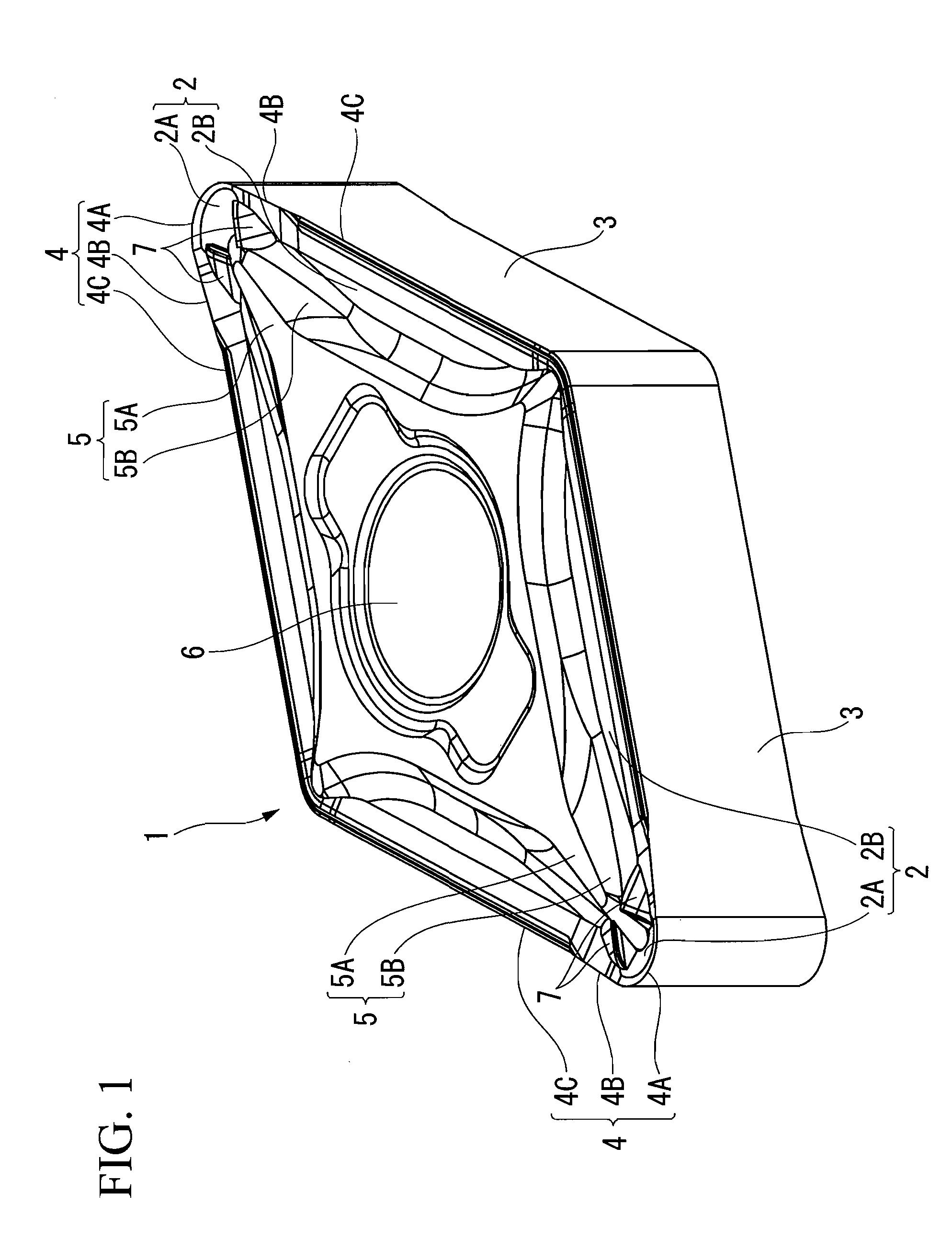
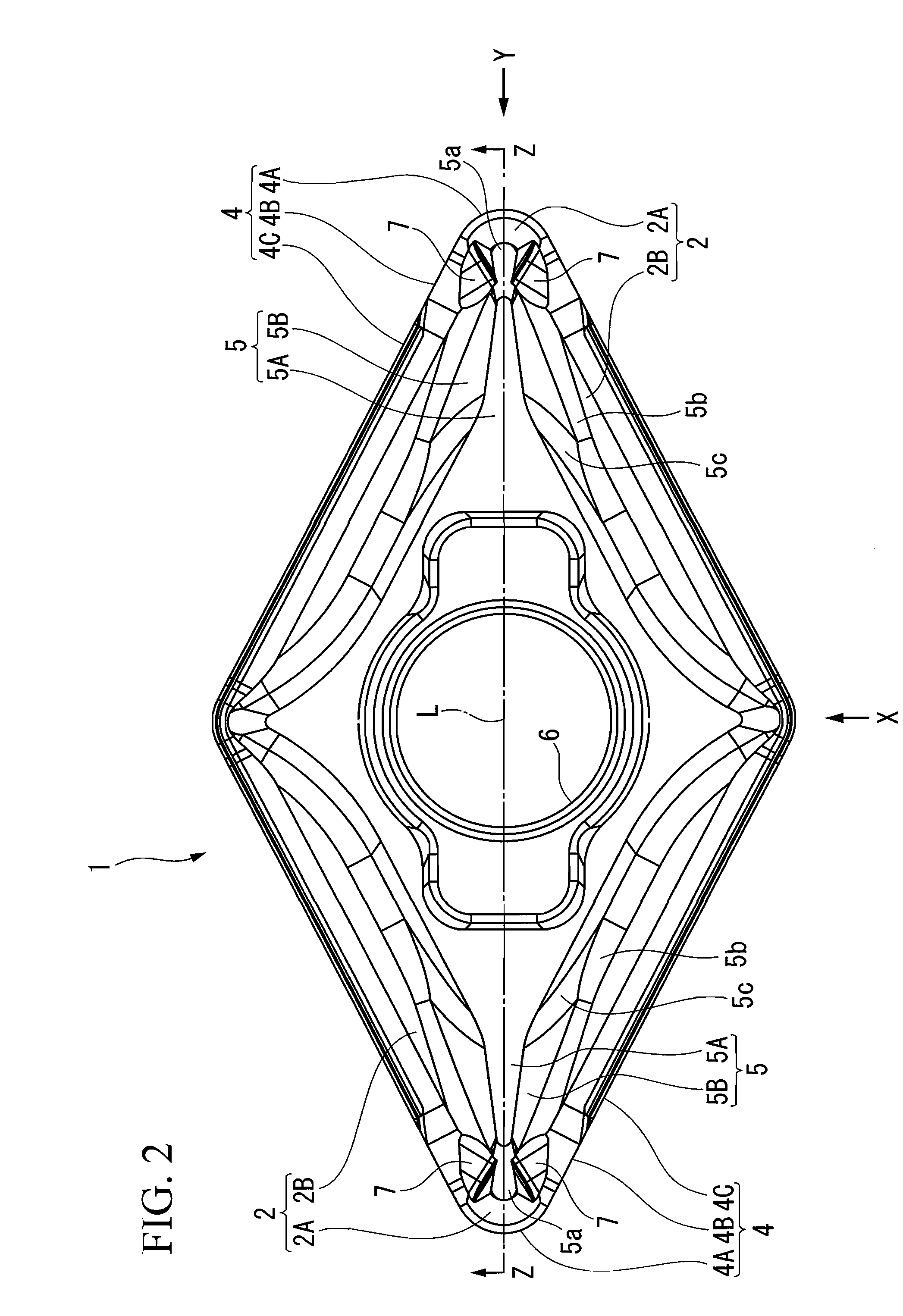
[0051]FIGS. 1 to 9 show a first embodiment of the present invention. According to the embodiment, the insert body 1 is formed in a polygonal plate shape (particularly a rhombic plate shape) by hard material such as sintered hard alloy. The insert body 1 is configured as a negative type insert in which rake faces 2 are formed on the pair of rhombus-shaped surfaces and flank faces 3 disposed in the vicinity of the rake faces 2 extend parallel to the thickness direction (up and down directions in FIGS. 3 to 5) of the insert body 1. In the insert body 1, the pair of rhombus-shaped surfaces is symmetrically formed to be reversible, is symmetrically formed to be rotated by 180 degrees about the central line of the rhombic plate surfaces, and is symmetrically formed with respect to planes extended in parallel to the thickness direction between rhombus-shaped acute corner portions and obtuse corner portions, respectively.

[0052]A cutting edge 4 is formed on peripheral border of the rake face...


PUM

PropertyMeasurementUnit
Angleaaaaaaaaaa
Widthaaaaaaaaaa
Heightaaaaaaaaaa

Abstract

In a cutting insert, a cutting edge is formed on a peripheral border of a rake face; a protruding section is formed on the rake face; a pair of convex sections is formed so as to extend toward the cutting edge; the convex sections face toward a corner portion; the convex sections include first wall surfaces and second wall surfaces; the first wall surfaces and the second wall surfaces are inclined surfaces that are inclined toward the rake face as those are farther from ridgelines intersecting with each other; and the intersection ridgelines intersect with a wall surface of the protruding section, at a position lower than a top portion of the protruding section in the corner portion side.

Description

[0001]Priority is claimed on Japanese Patent Application No. 2007-056975, filed Mar. 7, 2007, the contents of which are incorporated herein by reference.BACKGROUND OF THE INVENTION[0002]1. Field of the Invention[0003]The present invention relates to a cutting insert mounted on a replaceable insert turning tool and capable of reliably disposing of cutting chips produced under various cutting conditions from a medium cutting for cutting relatively a large amount to a light cutting such as a finish cutting for cutting a small amount.[0004]2. Description of the Related Art[0005]Such a cutting insert capable of reliably disposing of cutting chips produced under various cutting conditions from the medium cutting to the finish cutting is discussed in, for example, Japanese Unexamined Patent Application, First Publication No. 2006-272548. In the cutting insert, a breaker groove is formed along a cutting edge on a rake face. A protrusion of a boss surface extends to a corner portion of the c...

Claims


Application Information

Patent Timeline
IPC IPC(8): B26D1/00
CPCY10T407/24B23B2200/0452B23B2200/328B23B2200/321Y10T407/235Y10T407/245B23B27/143
Inventor YAMAZAKI, KAZUYASUGAWARA, KENJI
Owner MITSUBISHI MATERIALS CORP
Why Eureka
Try Eureka