Scanning probe microscope

a scanning probe and microscope technology, applied in the field of scanning probe microscopes, can solve the problems of user the position of the beam splitter deviating, and the damage or damage so as to prevent the user from touching the beam splitter, shorten the moving distance of the beam splitter, and prevent damage to the beam splitter

Active Publication Date: 2018-04-19
SHIMADZU CORP
View PDF10 Cites 0 Cited by
  • Summary
  • Abstract
  • Description
  • Claims
  • Application Information

AI Technical Summary

Benefits of technology

[0022]According to such a configuration, by regulating the rotational position of the operating portion by the stopper, the beam splitter can be reliably disposed at the insertion position or the retracted position.
[0023]According to the invention, the beam splitter rotates and moves within the housing. Therefore, it is possible to prevent the user from touching the beam splitter, and it is possible to prevent the beam splitter from being damaged or stains from adhering to the beam splitter. In addition, the moving distance of the beam splitter can be shortened. Therefore, it is possible to suppress the occurrence of deviation in the position of the beam splitter. That is, even when the beam splitter is configured to be movable, observation can be performed with high accuracy.

Problems solved by technology

Therefore, there is a possibility that the user touches the beam splitter.
When the user touches the beam splitter, the beam splitter may be damaged or stains may adhere to the beam splitter.
Further, since the moving distance of the beam splitter increases, there is a high possibility that the position of the beam splitter deviates.
That is, in the scanning probe microscope of the related art, when the beam splitter is configured to be movable, the accuracy of observation may decrease.

Method used


Image

  • Scanning probe microscope
  • Scanning probe microscope
  • Scanning probe microscope

Examples


Embodiment Construction

1. Overall Configuration of Scanning Probe Microscope

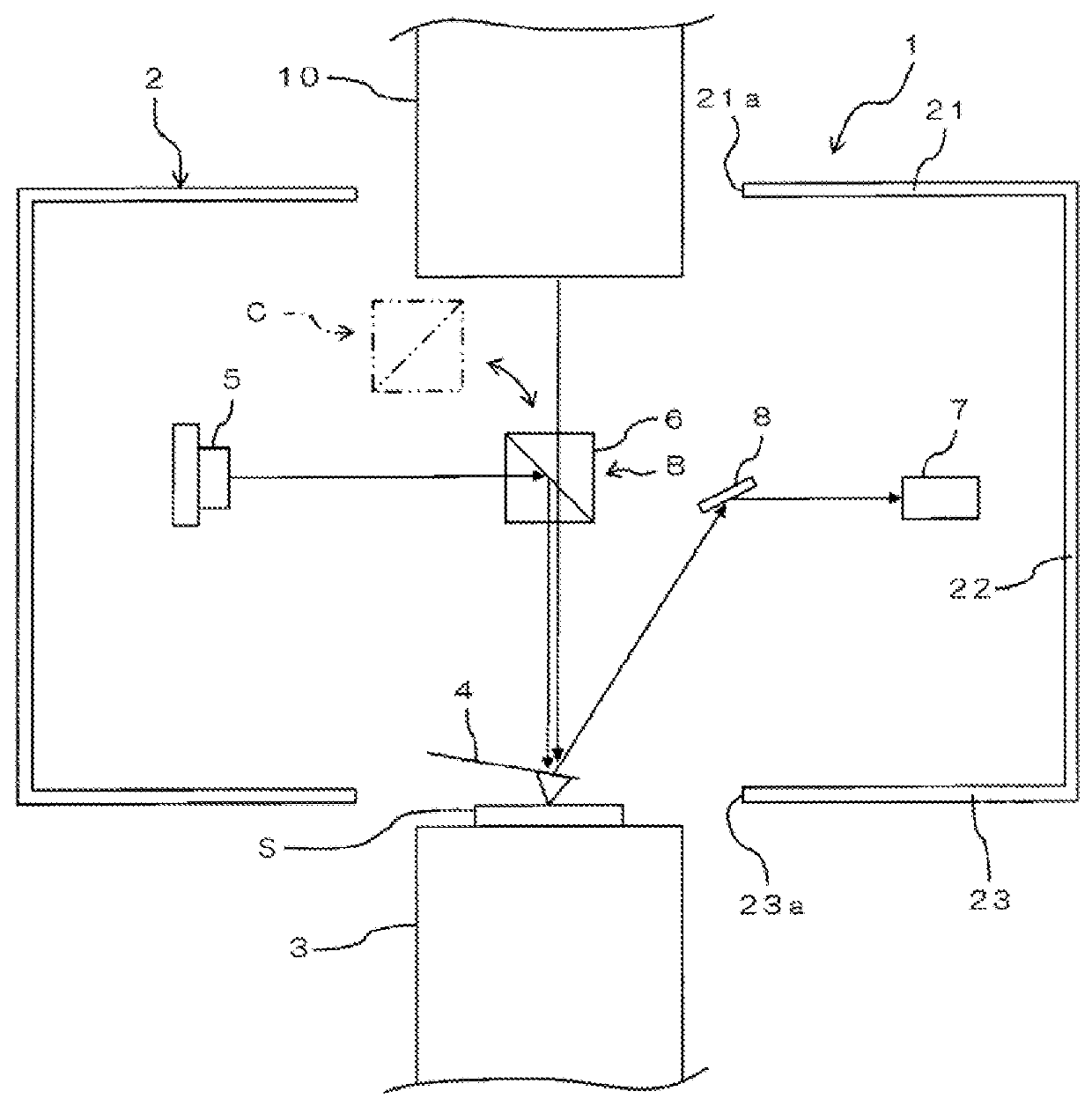
[0028]FIG. 1 is a cross-sectional view illustrating a configuration example of a scanning probe microscope 1 according to an embodiment of the invention. The scanning probe microscope 1 is, for example, an atomic force microscope (AFM). The scanning probe microscope 1 includes a housing 2, a stage 3, a cantilever 4, a beam source 5, a beam splitter 6, a beam receiving unit 7, and a mirror 8.

[0029]The housing 2 is formed in a hollow box shape. The housing 2 has a top surface 21, a side surface 22, and a bottom surface 23. On the top surface 21, a first opening portion 21a as an example of an opening port ion is formed. On the bottom surface 23, a second opening portion 23a is formed. The first opening portion 21a of the top surface 21 and the second opening portion 23a of the bottom surface 23 are disposed to face each other in the vertical direction. An optical microscope 10 is placed on the top surface 21. The optical microscope ...


PUM


Abstract

Provided is a scanning probe microscope capable of performing observation with high accuracy even when a beam splitter is configured to be movable.
When checking positions of a sample and a cantilever in a scanning probe microscope, by disposing an optical microscope to face a first opening portion of a top surface of a housing, and by gripping and rotating an operating portion provided on a side surface of the housing, a user rotates and moves a beam splitter held by a holding portion in the housing, and retracts the beam splitter from the field of view of the optical microscope. Therefore, the beam splitter can always be disposed in the housing, and the user can be prevented from touching the beam splitter. As a result, it is possible to prevent the beam splitter from being damaged or stains from adhering to the beam splitter. Further, the moving distance of the bears splitter 6 can be shortened. Therefore, it is possible to suppress the occurrence of a deviation in the position of the beam splitter.

Description

BACKGROUND OF THE INVENTIONField of the Invention[0001]The present invention relates to a scanning probe microscope having a mechanism which moves a beam splitter.Description of the Related Art[0002]From the related art, a scanning probe microscope has been used as an apparatus for inspecting a fine surface shape of a sample. In the scanning probe microscope, by relatively moving the probe to the surface of the sample and scanning the surface, a change in a physical quantity (such as a tunnel current or an atomic force) acting between the probe and the sample surface during the scanning is detected. Further, by feedback-controlling the relative position of the probe to constantly keep the physical quantity during scanning, the surface shape of the sample can be measured on the basis of the feedback amount.[0003]As such a scanning probe microscope, an apparatus having an observation window for checking the positions of the sample and the probe is used. In the scanning probe microscop...

Claims


Application Information

Patent Timeline
Patent Type & Authority Applications(United States)
IPC IPC(8): G01Q30/02G01Q20/02
CPCG01Q30/025G01Q20/02
Inventor KOBAYASHI, KANJIHIRADE, MASATO
Owner SHIMADZU CORP
Why Eureka
Try Eureka