Decompression heat-insulating pipe structure

a heat-insulating pipe and decompression technology, which is applied in the direction of domestic cooling apparatus, charge manipulation, furnaces, etc., can solve the problems of difficult decompression, inability to exhibit heat-insulating performance, and inability to decompress, so as to achieve easy assembly and suppress the effect of thermal expansion deformation

Active Publication Date: 2020-07-14
TOYOTA JIDOSHA KK
View PDF26 Cites 0 Cited by
  • Summary
  • Abstract
  • Description
  • Claims
  • Application Information

AI Technical Summary

Benefits of technology

[0005]The present disclosure has been made in view of the foregoing, and exemplary embodiments relate to providing a decompression heat-insulating pipe structure that can exhibit the desired heat-insulating performance and is easy to assemble.
[0007]According to the present disclosure, when the space between the inner tube and the outer tube is decompressed, the inner tube and the outer tube are caused to relatively approach each other, and so the first elastic seal member is compressed between the first flange and the third flange, and the second elastic seal member is compressed between the second flange and the fourth flange. Since the first elastic seal member and the second elastic seal member are compressed in the axial direction in which the dimensional accuracy of the inner tube and the outer tube is relatively high, a high sealing property can be obtained even when the dimensional accuracy in the radial direction of the inner tube and the outer tube is not high. Therefore, the space between the inner tube and the outer tube can be decompressed reliably and high heat-insulating performance can be obtained. In addition, only through insertion of the inner tube into the outer tube, the first elastic seal member and the second elastic seal member can be disposed reliably between the first flange and the third flange and between the second flange and the fourth flange, respectively, so as to be sandwiched therebetween, and so high assembly performance can be provided.
[0011]According to the present disclosure, when the space between the inner tube and the outer tube is decompressed, the inner tube and the outer tube are caused to relatively approach each other, and so the first elastic seal member is compressed between the first flange and the third flange, and the second elastic seal member is compressed between the second flange and the fourth flange. Since the first elastic seal member and the second elastic seal member are compressed in the axial direction in which the dimensional accuracy of the inner tube and the outer tube is relatively high, a high sealing property can be obtained. Therefore, the space between the inner tube and the outer tube can be decompressed reliably and high heat-insulating performance can be obtained. In addition, when the axial dimension of the inner tube changes due to thermal expansion or thermal shrinkage, for example, the first outer tube and the second outer tube slide with respect to each other in the axial direction. Therefore, the changed dimension can be absorbed and the sealed state with the first elastic seal member and the second elastic seal member can be can be kept.
[0013]According to the present disclosure, since the O-ring is disposed between the first short-tube portion and the second short-tube portion, which have higher dimensional accuracy in the radial direction than the first long-tube portion and the second long-tube portion, a space between the first outer tube and the second outer tube can be sealed reliably.
[0015]According to the present disclosure, the first short-tube portion and the second short-tube portion are disposed at the axially central position of the outer tube that is as far as possible from the axially opposite ends of the outer tube to which heat from the inner tube is easily transferred. Therefore, a temperature rise of the first short-tube portion, the second short-tube portion, and the O-ring can be suppressed, and so deformation thereof due to thermal expansion can be suppressed. Therefore, the sealing property between the first outer tube and the second outer tube can be kept high.
[0016]According to the present disclosure, a decompression heat-insulating pipe structure that can exhibit the desired heat-insulating performance and is easy to assemble can be provided.

Problems solved by technology

However, when the technique disclosed in JP 2003-314785 A is used, if the dimensional accuracy in the radial direction of the inner tube and the outer tube is low, there may be adverse effect on the heat-insulating performance and the assembly performance.
Therefore, in such a case, the space between the inner tube and the outer tube is difficult to be sealed with an elastic seal member, such as rubber, and therefore is difficult to be decompressed, and so the desired heat-insulating performance may not be exhibited.
Therefore, in such a case, an elastic seal member is difficult to be disposed in a space between the inner tube and the outer tube, and so the assembly performance may deteriorate.

Method used


Image

  • Decompression heat-insulating pipe structure
  • Decompression heat-insulating pipe structure
  • Decompression heat-insulating pipe structure

Examples


first embodiment

[0027]Next, a first embodiment of the present disclosure will be described in detail with reference to the drawings.

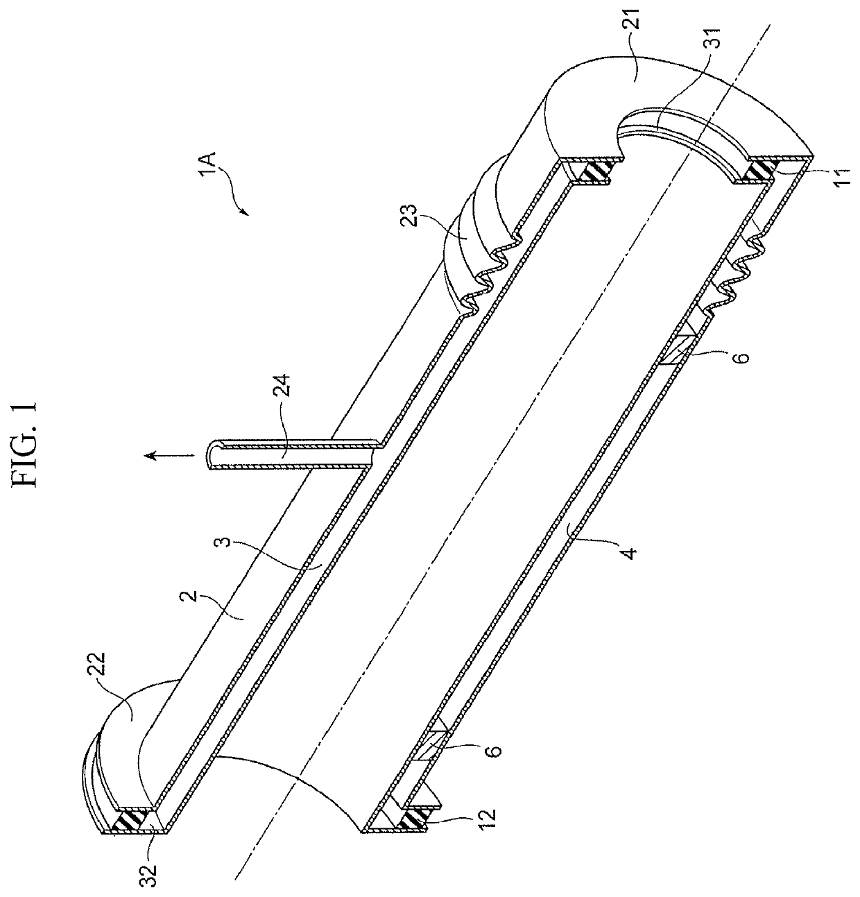
[0028]FIG. 1 is a perspective cross-sectional view of a decompression heat-insulating pipe structure in accordance with the first embodiment.

[0029]A decompression heat-insulating pipe structure 1A has a double-tube structure including an outer tube 2 and an inner tube 3 inserted into the outer tube 2. A space between axially one end of the outer tube 2 and axially one end of the inner tube 3 is sealed with a first elastic seal member 11, while a space between the axially other end of the outer tube 2 and the axially other end of the inner tube 3 is sealed with a second elastic seal member 12.

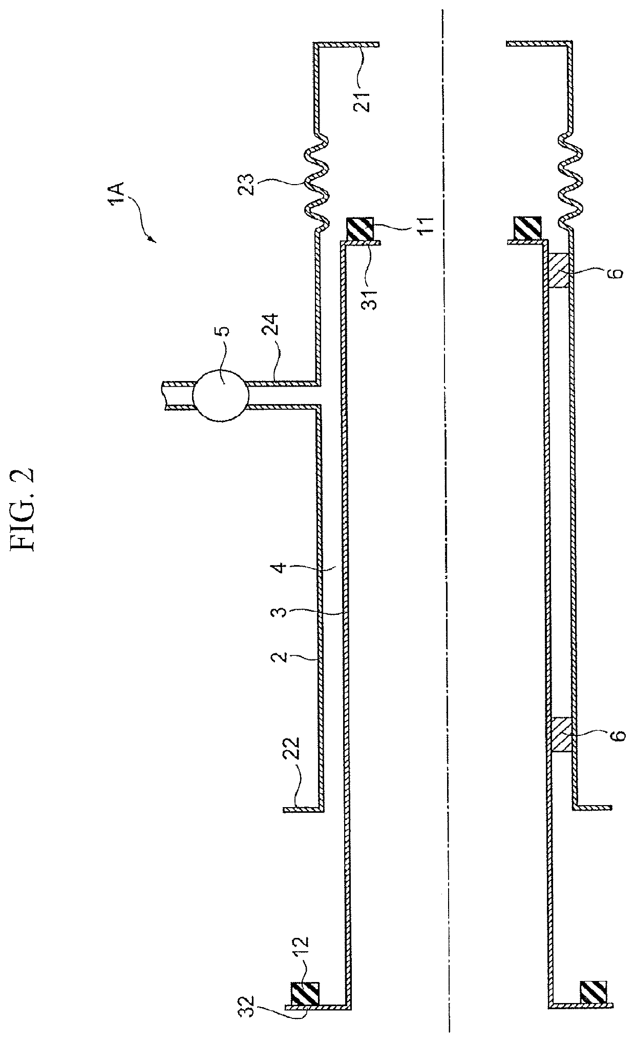
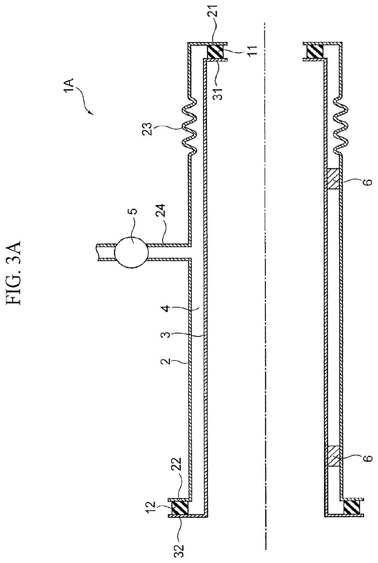
[0030]The outer tube 2 connects with an exhaust channel 24 leading to a vacuum pump 5 (see FIG. 2). Air between the outer tube 2 and the inner tube 3 is exhausted through the exhaust channel 24 so that a space 4 between the outer tube 2 and the inner tube 3 can be decompressed. Suc...

second embodiment

[0058]Next, a second embodiment of the present disclosure will be described in detail with reference to the drawings. It should be noted that the same components as those in the first embodiment are denoted by the same reference numerals and detailed description will be omitted.

[0059]FIG. 4A is a cross-sectional view showing a state before the internal space of an inner tube of a decompression heat-insulating pipe structure in accordance with the second embodiment is heated. FIG. 4B is a cross-sectional view showing a state in which the internal space of the inner tube of the decompression heat-insulating pipe structure in accordance with the second embodiment is heated.

[0060]A decompression heat-insulating pipe structure 1B in this embodiment is characterized in that an outer tube 2 is formed with a first outer tube 2A and a second outer tube 2B so that the axial length of the outer tube 2 is made adjustable.

[0061]The decompression heat-insulating pipe structure 1B has the outer tu...

third embodiment

[0084]Next, a third embodiment of the present disclosure will be described in detail with reference to the drawings. It should be noted that the same components as those in the first embodiment are denoted by the same reference numerals and detailed description will be omitted.

[0085]FIG. 6 is a cross-sectional view showing an exemplary configuration of a decompression heat-insulating pipe structure in accordance with the third embodiment.

[0086]This embodiment is characterized in that an inner tube 3 of a decompression heat-insulating pipe structure 1C is formed with a first inner tube 3A and a second inner tube 3B so that the axial length of the inner tube 3 is made adjustable.

[0087]The decompression heat-insulating pipe structure 1C has an outer tube 2 and the inner tube 3. The outer tube 2 has a first flange 71 extending radially inward from its axially one end, and has a second flange 72 extending radially inward from its axially other end.

[0088]The inner tube 3 has a first inner...


PUM

PropertyMeasurementUnit
decompression heat-insulatingaaaaaaaaaa
heat-insulating performanceaaaaaaaaaa
radial dimensionaaaaaaaaaa

Abstract

A decompression heat-insulating pipe structure that can exhibit the desired heat-insulating performance and is easy to assemble. In the structure, a space between ends of inner and outer tubes is decompressed. The outer tube includes a first flange, which extends radially inward from an axially one end thereof, and a second flange, which extends radially outward from the axially other end thereof. The inner tube includes a third flange, which extends radially inward from an axially one end thereof and is opposed to the first flange at an axially inward position of the first flange, and a fourth flange, which extends radially outward from the axially other end thereof and being opposed to the second flange at an axially outward position of the second flange. First and second elastic seal members are disposed between the first and third flanges and between the second and fourth flanges, respectively.

Description

CROSS REFERENCE TO RELATED APPLICATIONS[0001]The present application claims priority from Japanese patent application JP 2017-021632 filed on Feb. 8, 2017, the content of which is hereby incorporated by reference into this application.BACKGROUNDTechnical Field[0002]The present disclosure relates to a decompression heat-insulating pipe structure in which a space between an inner tube and an outer tube is decompressed.Background Art[0003]Conventionally, there has been known a technique of a decompression heat-insulating pipe structure in which a space between ends of an outer tube and an inner tube is sealed with an elastic rubber member for decompressing the space between the inner tube and the outer tube (see JP 2003-314785 A).SUMMARY[0004]However, when the technique disclosed in JP 2003-314785 A is used, if the dimensional accuracy in the radial direction of the inner tube and the outer tube is low, there may be adverse effect on the heat-insulating performance and the assembly per...

Claims


Application Information

Patent Timeline
Patent Type & Authority Patents(United States)
IPC IPC(8): F16L59/065F27D99/00F27D3/00B65D81/38F16L51/02C21D9/00F16L51/00F16L27/11F16L27/107F16L23/22F16L9/18F16L59/14F27D3/18C21D1/773F16L39/04
CPCF16L59/143C21D9/0006B65D81/3841F27D3/0025F16L9/18F16L23/22F16L27/107F16L51/00F16L59/065F16L27/11F27D99/0073F16L59/14F27D3/18F16L51/025F27D3/0033F16L39/04C21D1/773
Inventor YAMASHITA, OSAMU
Owner TOYOTA JIDOSHA KK
Why Eureka
Try Eureka