
System and method for correction of inhomogeneous fields

a technology of inhomogeneous field and system, applied in the field of system and method for correction of inhomogeneous field, can solve the problems of reducing the precision and accuracy of position measurements, and the homogeneity of the localization field

Active Publication Date: 2008-09-11
ST JUDE MEDICAL ATRIAL FIBRILLATION DIV
View PDF47 Cites 36 Cited by
  • Summary
  • Abstract
  • Description
  • Claims
  • Application Information

AI Technical Summary

Benefits of technology

[0015]An advantage of the present invention is that it provides a localization system that corrects for inhomogeneities in the localization field within which positions are measured.

Problems solved by technology

It is known, however, that the localization field may not be homogeneous.
These inhomogeneities potentially reduce the precision and accuracy of the position measurements made by the localization system.

Method used


Image

  • System and method for correction of inhomogeneous fields
  • System and method for correction of inhomogeneous fields
  • System and method for correction of inhomogeneous fields

Examples


Embodiment Construction

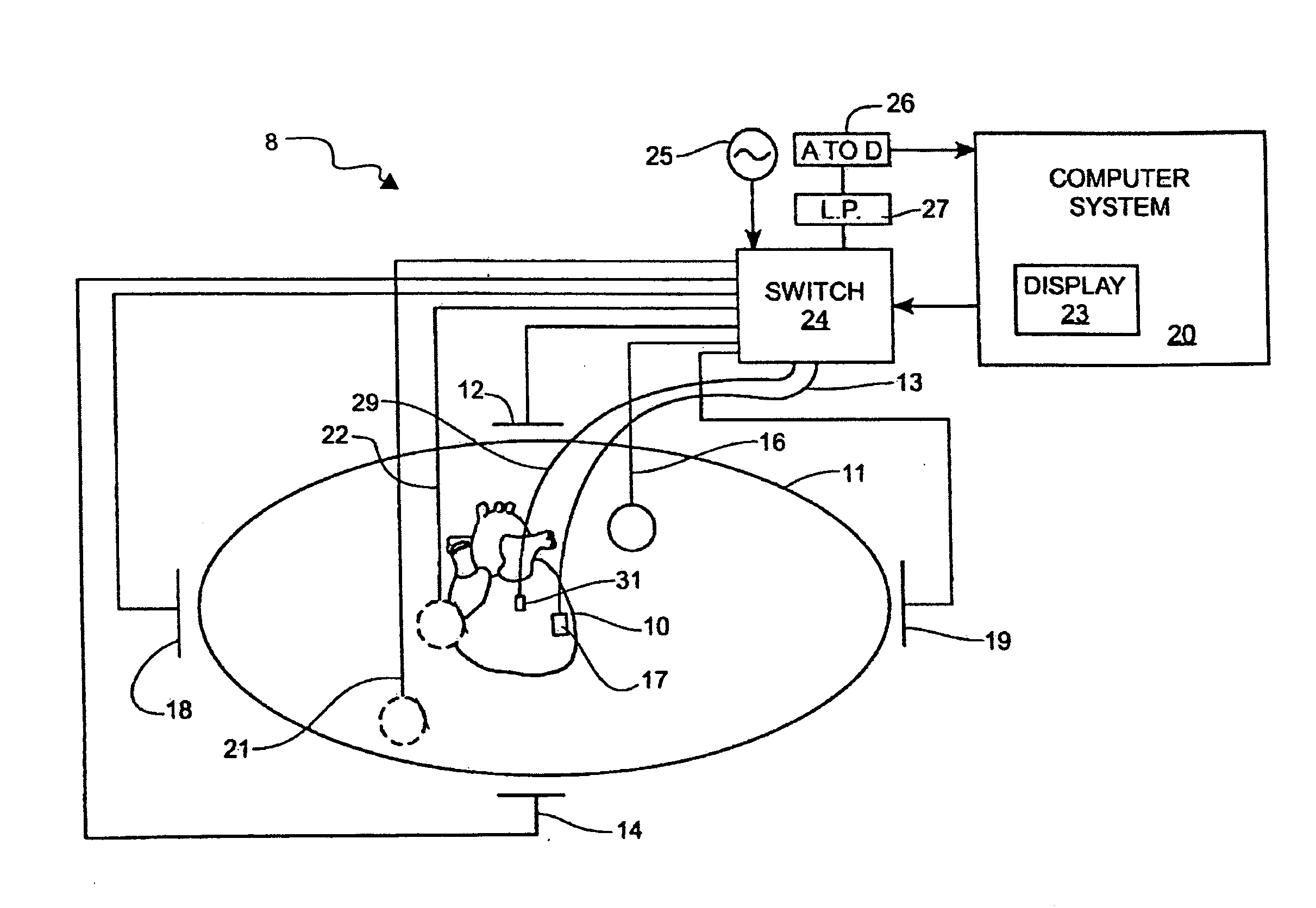
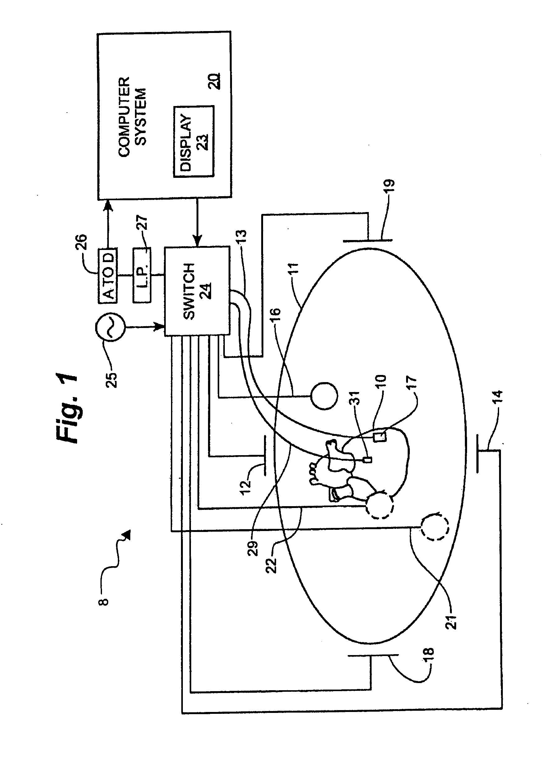
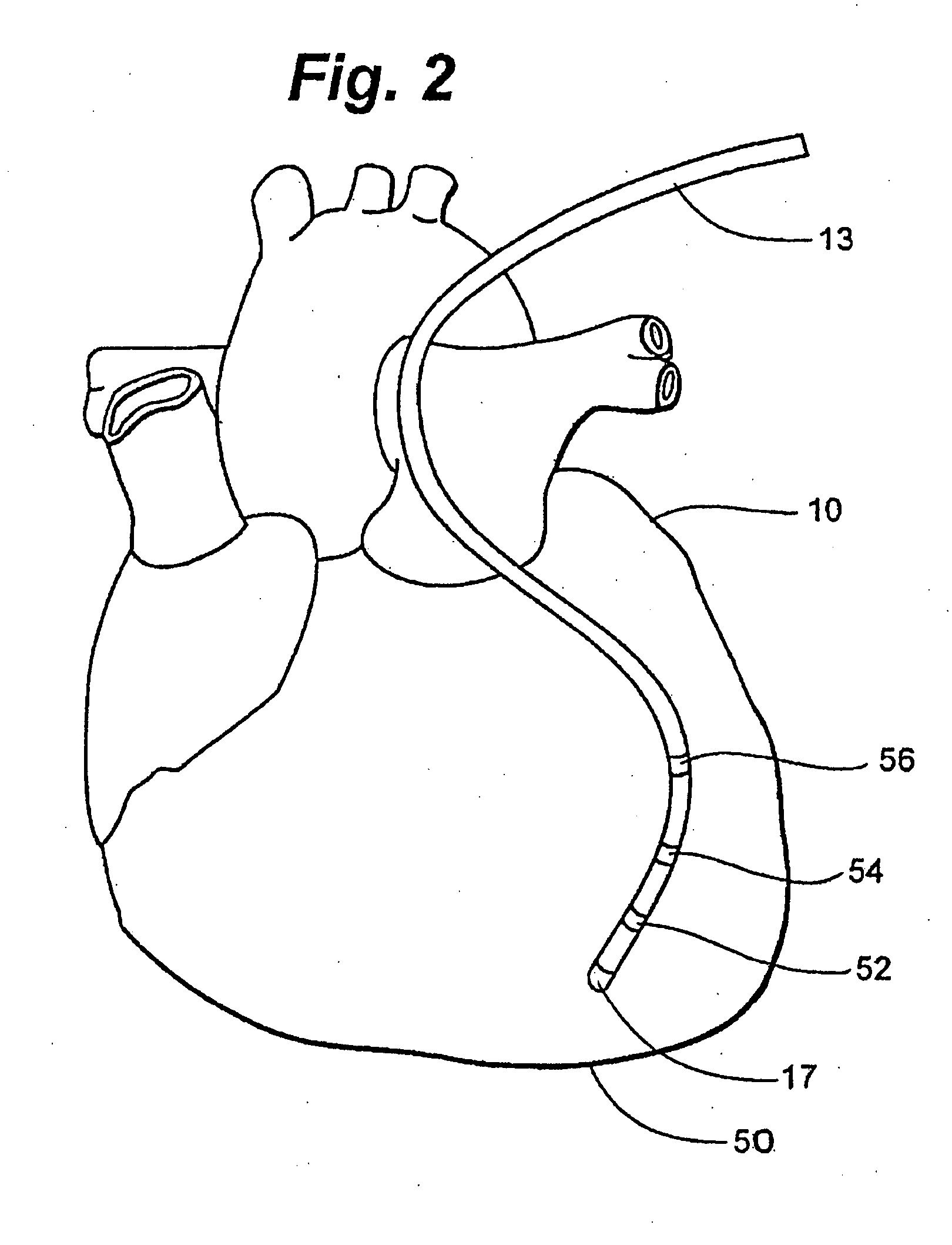
[0023]The present invention provides a method and system for accounting for inhomogeneities in a localization field. Localization fields are often employed in procedures carried out within a human body, and in particular in cardiac diagnostic and therapeutic procedures. Therefore, for purposes of illustration, the invention will be described in detail in the context of a localization system utilized in a cardiac electrophysiology procedure. It is contemplated, however, that the present invention may be practiced to good advantage in other contexts, including, for example, to measure internal distortions in a manufacturing environment. Further, though the invention will generally be illustrated in two-dimensions, one of ordinary skill in the art will appreciate how to apply the principles described herein in any number of dimensions. For example, the present invention may be practiced in the time domain in order to compensate for changes in localization fields that occur with respira...


PUM


Abstract

A method for determining a location of an object in a three-dimensional localization field created by a localization system includes the following steps: providing a catheter having known spacing between electrodes; providing a lookup table of data correlating locations of an object within the localization field with measurements made by the localization system; placing the catheter into the localization field; using the localization system to determine the location of the electrodes based on the lookup table; calculating an observed distance between electrodes; comparing the observed distance to the known electrode spacing; and adjusting the lookup table to more accurately measure the spacing of the electrodes. A Kernel function, such as the derivative of a Gaussian function, may be used to update the lookup table.

Description

CROSS-REFERENCE TO RELATED APPLICATIONS[0001]This application is related to U.S. application Ser. No. ______, filed concurrently herewith, entitled “System and Method for Local Deformable Registration of a Catheter Navigation System to Image Data or a Model” (Attorney Docket No. 0G-042000US / 82410-0161), which is hereby incorporated by reference as though fully set forth herein.BACKGROUND OF THE INVENTION[0002]a. Field of the Invention[0003]The instant invention relates to localization systems that measure position utilizing localization fields. In particular, the instant invention relates to a system and method to account for inhomogeneity of the localization field.[0004]b. Background Art[0005]It is well known to generate heart chamber geometry in preparation for cardiac diagnostic or therapeutic procedures. Often, a mapping catheter is introduced into the heart chamber of interest and moved around within the heart chamber, either randomly, pseudo-randomly, or according to one or mo...

Claims


Application Information

Patent Timeline
Patent Type & Authority Applications(United States)
IPC IPC(8): A61N1/00G06F19/00A61B5/296
CPCA61B5/0422A61B2019/5289A61B6/503A61B19/44A61B19/50A61B19/52A61B19/5244A61B2017/00053A61B2017/00243A61B2017/00482A61B2017/00703A61B2017/00725A61B2019/505A61B2019/5251A61B2019/5253A61B5/06A61B90/36A61B2034/2053A61B34/20A61B2090/364A61B90/90A61B34/10A61B2034/105A61B2034/2051A61B5/062A61B5/287
Inventor OLSON, ERIC S.
Owner ST JUDE MEDICAL ATRIAL FIBRILLATION DIV
Learn More