
Collection and distribution system

a technology of collection and distribution system and rocket launcher, which is applied in the field of rocket launcher racing competitions, can solve the problems of not being able to ‘scheduled’ rocket launch, not appealing to a limited audience, and not attracted significant sponsorship or media/broadcast rights

Inactive Publication Date: 2008-09-11
ROCKET RACING
View PDF50 Cites 56 Cited by
  • Summary
  • Abstract
  • Description
  • Claims
  • Application Information

AI Technical Summary

Benefits of technology

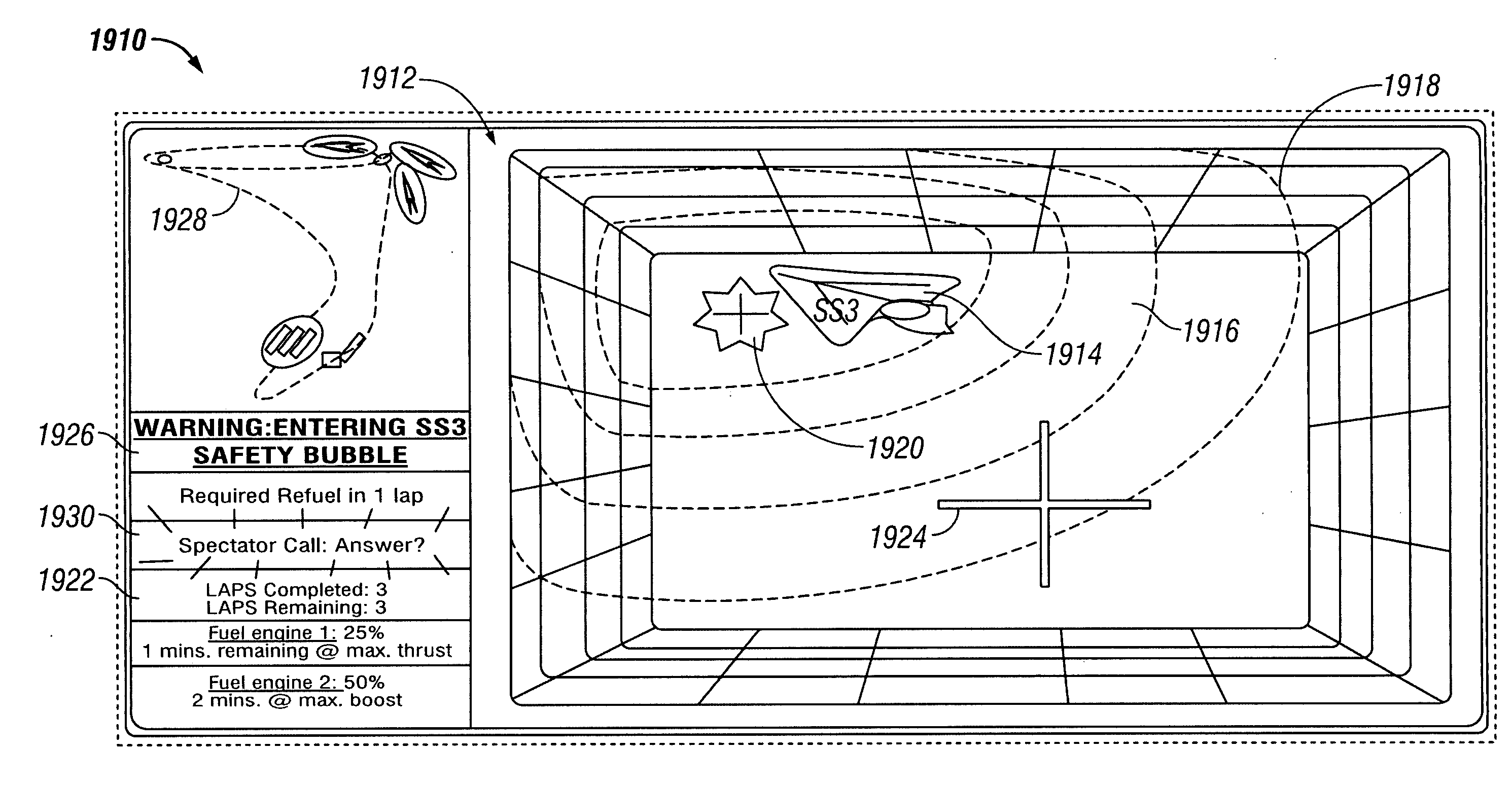
[0011]An embodiment of the present invention relates to a data collection system that collects a first set of data from one or more aerial vehicles in an aerial race, and collects a second set of data from one or more sources apart from the one or more aerial vehicles. The second set of data comprises data regarding the aerial race. The system provides at least some of the first and second sets of data to one or more computers, and the one or more computers processes the data and provides the processed data to one or more end-users. The second set of data is preferably from one or more ground-based sources and comprises images, including but not limited to video images. The first set of data can include geospatial data of at least one of the aerial vehicles. End-users include but are not limited to race officials and broadcasters. In one embodiment, the one or more aerial vehicle is a rocket-powered vehicle. Both the first set of data and the second set of data are preferably real-time data.

Problems solved by technology

Car racing, however, appeals to a limited audience that primarily comprises race enthusiasts.
Manned rocket launches have traditionally been high visibility events that garner tremendous public interest beyond enthusiast groups, but which have never attracted significant sponsorships or media / broadcast rights.
This is because rocket launches typically cannot be ‘scheduled’, as their actual launch time and date depend on when the payload and rocket are ready for deployment, and on weather conditions.
Launch delays are commonplace and lead to great difficulty when scheduling network broadcast time.
Further, they desire that the events involve people (e.g., heroes) that participate in the events, which can make the launch of satellites by unmanned rockets uninteresting and inconsequential to the public.
Unfortunately, conventional manned rockets have been government owned and operated (e.g., the U.S. Space Shuttle and the Russian Soyuz), which do not actively market sponsorships.
Although the X PRIZE COMPETITION is an excellent introduction into the realm of privately owned rocket-powered vehicles, it does not lend itself to public involvement in a competition atmosphere and to the marketing interest of other competitions, such as car racing and yacht racing competitions.

Method used


Image

  • Collection and distribution system
  • Collection and distribution system
  • Collection and distribution system

Examples


example rocket -

EXAMPLE ROCKET-POWERED VEHICLE COMPETITION

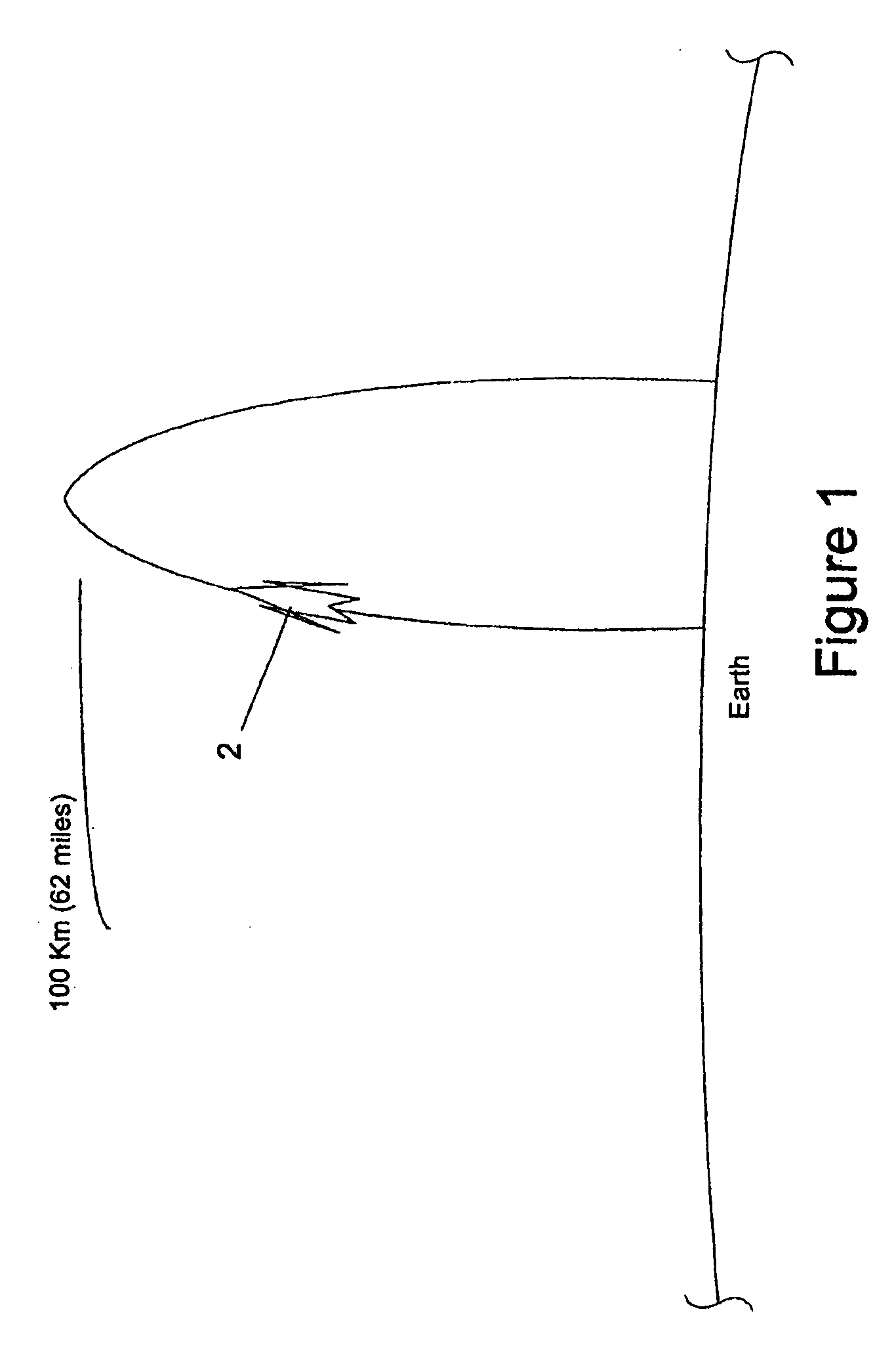
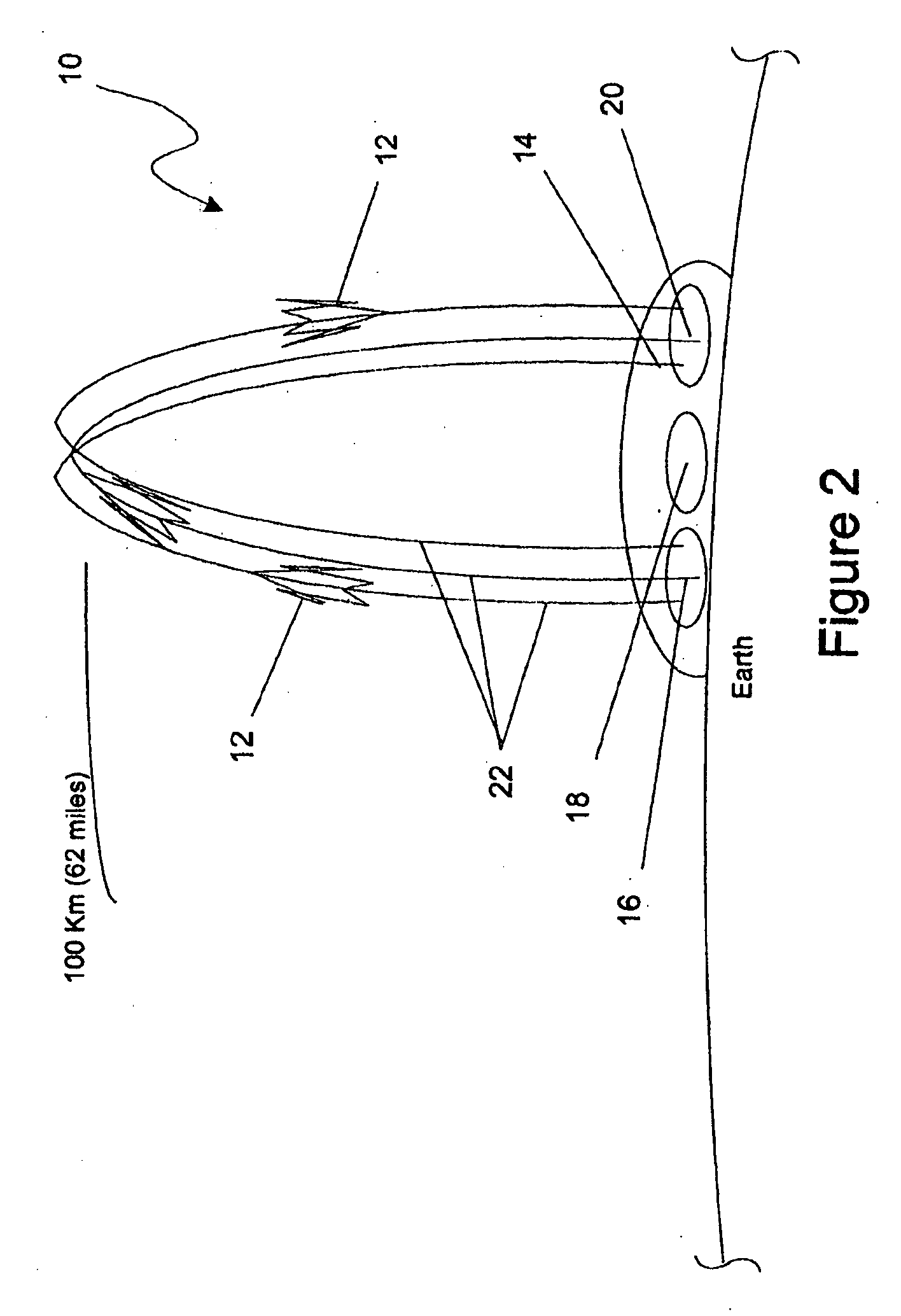
[0048]Although multiple embodiments of the present invention describe a preferred minimum height of 100 km, the multiple embodiments of the present invention are not to be construed as limited to this height, rather the multiple embodiments of the present invention can comprise any distance from about 1 km to about 250 km, or any other distance further described herein. In embodiments of the present invention, this distance is preferably from about 255 km to about 200 km and more preferably from about 50 km to about 150 km. Further, the term “rocket” as used throughout the specification and claims is used to maintain simplicity and is intended to include not only rocket-powered vehicles, but also jet-powered and propeller driven vehicles. In addition, disclosures made herein relating to rocket fuel or its components are also intended to include jet fuel, or any other vehicle fuel, and / or their components. Although embodiments of the present ...

example 1

Rocket Powered Vehicle

[0061]Referring now to FIGS. 6 and 8, an example rocket-powered vehicle 12, according to an embodiment of the present invention, is illustrated for use with rocket-powered vehicle competition 10 and the block diagram of FIG. 3. Rocket-powered vehicle 12 is a human-carrying, rocket powered, reusable vehicle, which may include aviation stages (not shown) and is capable of traveling at supersonic speeds. A significant portion of a flight for rocket-powered vehicle 12 should be powered by rocket engines, such as the take-off portion of flight. Each team may provide a document that describes the general nature and configuration of its vehicle, propellants, vehicle non-propellant mass, take-off and landing modes, and its intended flight plans.

[0062]As shown in FIG. 6, rocket-powered vehicle 12 generally comprises vehicle 26, propulsion system 28 comprising propellant 30, and flight system 32. Vehicle 26 is capable of carrying one or more human occupants (not shown) d...

example 2

Spaceport

[0067]Referring now to FIGS. 4, 5 and 5a, spaceport 14 is generally illustrated. In this embodiment of the present invention, spaceport 14 provides a pre-determined location from which rocket-powered vehicles 12 can takeoff and land, and from which spectators may view rocket-powered vehicle competition 10. FIG. 4 is a perspective view of fair and exhibition grounds portion 68 of spaceport 14, which permits spectators to evaluate exhibits and view takeoff and / or landing of rocket-powered vehicles 12 occurring in distant portions of spaceport 14. FIG. 5 is top-view diagram of spaceport 14, and FIG. 5A shows portions of the diagram of FIG. 5. Spaceport 14 may be located in a remote area, such as in the deserts of Nevada and / or New Mexico, in which an exclusive, controlled airspace may be maintained during rocket-powered vehicle competition 10.

[0068]In the embodiment of the invention illustrated in FIG. 5A, spaceport 14 generally comprises launch portion 16, spectator portion 1...


PUM


Abstract

A collection and distribution system wherein information is collected from one or more aerial vehicles and from one or more ground-based sources before being processed and provided to an end-user.

Description

CROSS-REFERENCE TO RELATED APPLICATIONS[0001]This application is a continuation-in-part application of U.S. patent application Ser. Nos. 11 / 875,745 and 11 / 538,014 and those applications are incorporated herein by reference. This application is also related to U.S. Provisional Patent Application Ser. No. 60 / 862,203, entitled “Rocket-Powered Vehicle Reality System”, filed Oct. 19, 2006, which is incorporated herein reference. This application also claims priority to and the benefit of the filing of U.S. Provisional Patent Application Ser. No. 60 / 957,603, entitled “Rocket-Powered Vehicle Racing Reality System”, filed Aug. 23, 2007, and the specification thereof is incorporated herein by reference.COPYRIGHTED MATERIAL[0002]©2004-2006, Rocket Racing, Inc. A portion of the disclosure of this patent document and of the related applications listed above contains material that is subject to copyright protection. The owner has no objection to the facsimile reproduction by anyone of the patent...

Claims


Application Information

Patent Timeline
Patent Type & Authority Applications(United States)
IPC IPC(8): G05D1/00
CPCA63K3/00B64G3/00B64D27/023
Inventor DIAMANDIS, PETER H.WHITELAW, GRANGERD'ANGELO, MICHAEL R.
Owner ROCKET RACING
Learn More