
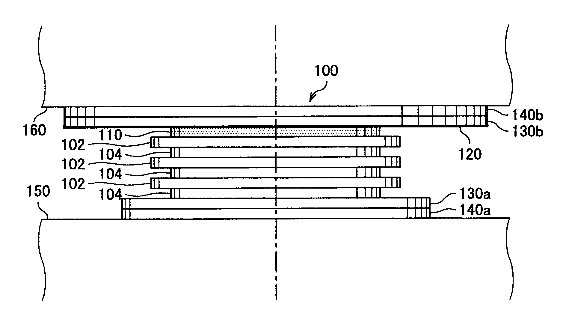
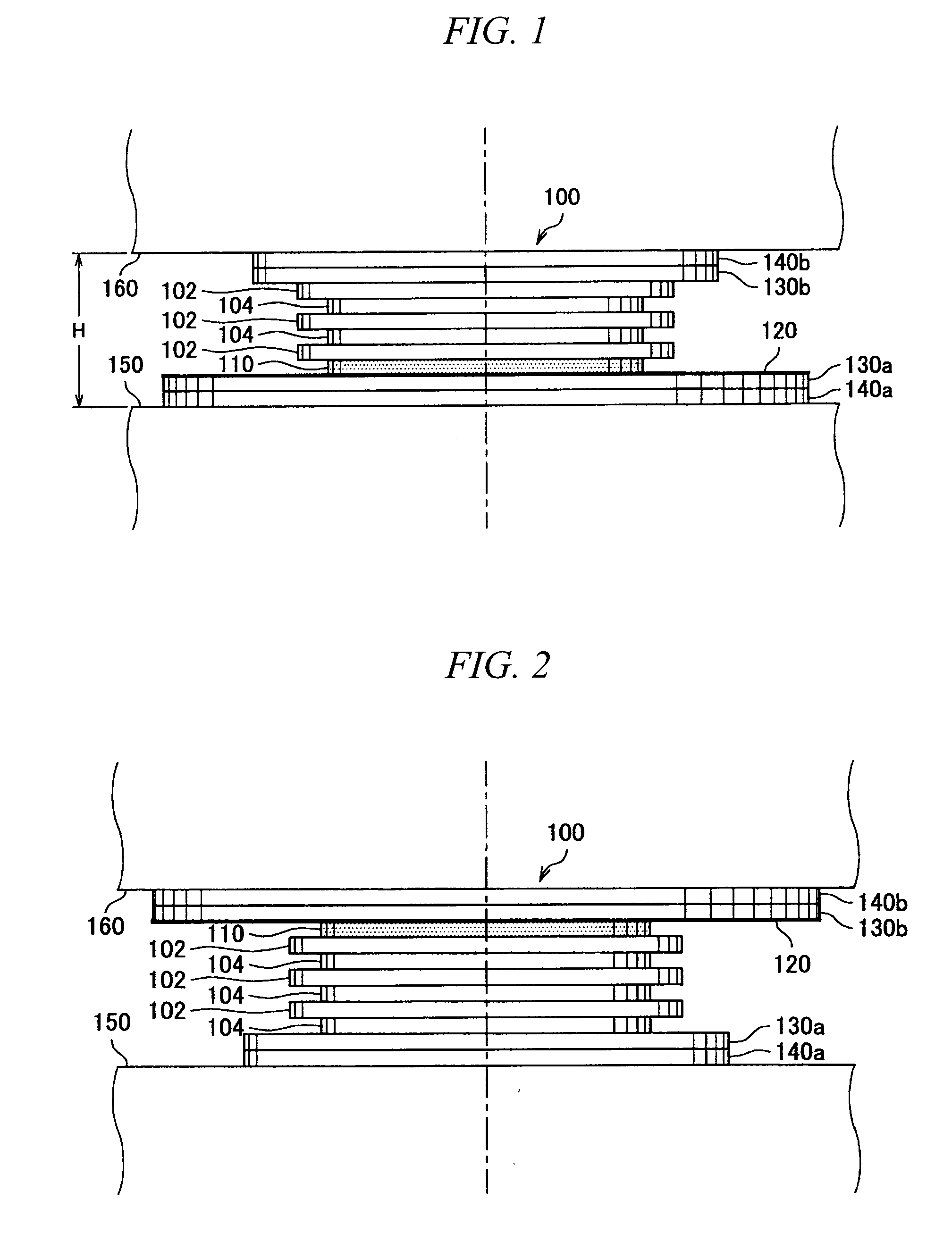
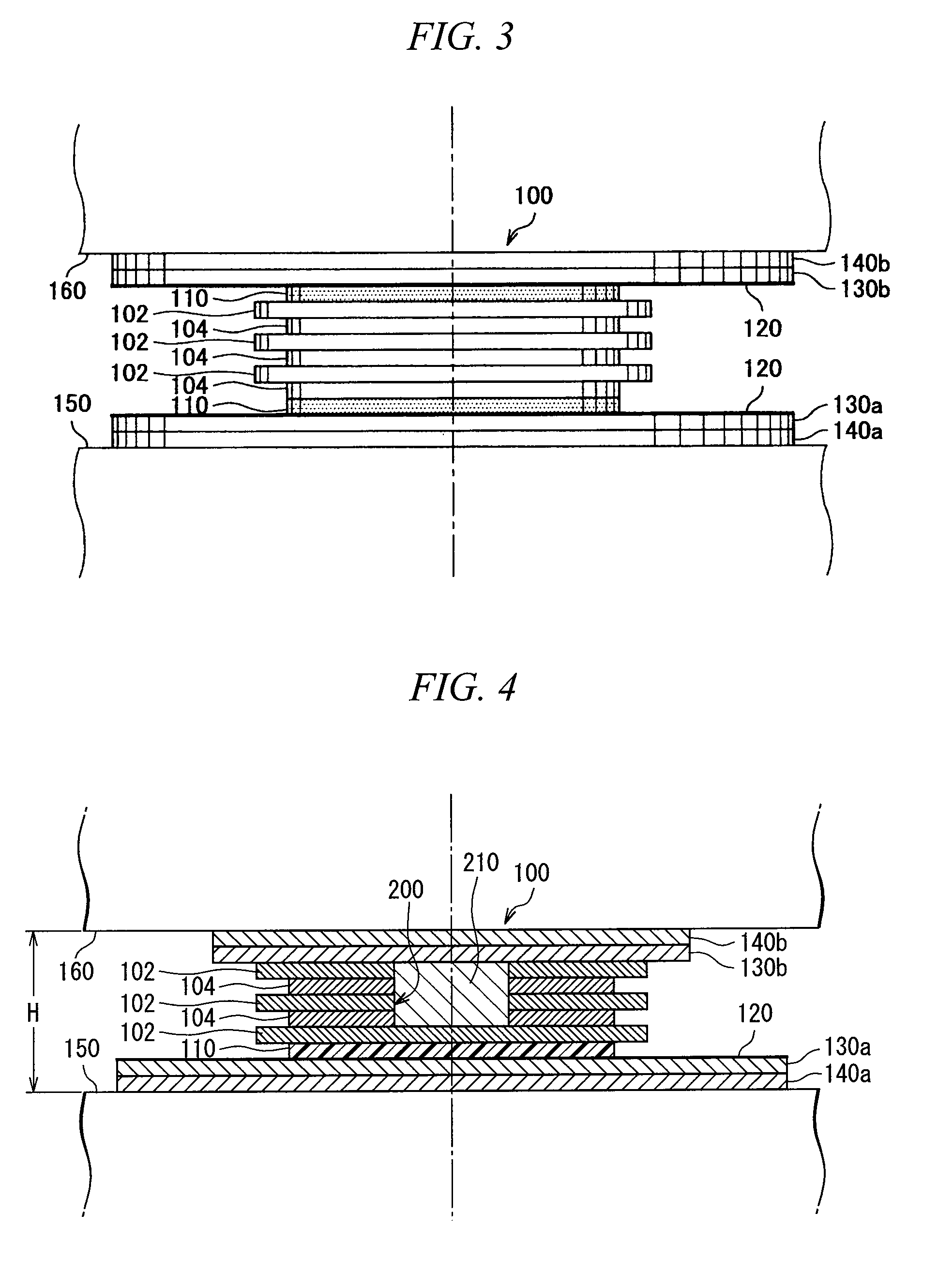
Sliding-type laminated plate bearing and structure

a technology of laminated plates and bearings, which is applied in the direction of linear bearings, mechanical equipment, shock-proofing, etc., can solve the problems of inclination of the upper construction body, and local deviation of the rubber plate and steel plate, so as to increase the deformation capacity, and reduce the effect of frictional attenuation

Inactive Publication Date: 2008-09-18
NIPPON STEEL CORP
View PDF6 Cites 27 Cited by
  • Summary
  • Abstract
  • Description
  • Claims
  • Application Information

AI Technical Summary

Benefits of technology

[0019]A lubricating agent such as fluorine resin coating or grease may be coated on the surface of the second smooth member as surface treatment for reducing the friction between the first smooth member and the second smooth member. Further, a plug portion, for example, a metal plug made of lead or tin may be inserted axially at the center of the laminated portion.
[0023]According to the present invention, it is possible to divide rigid members and elastic members of a laminated portion or the first smooth member and the second smooth member into small and light-weight components and bring them into a construction site. Therefore, they can be installed or exchanged more efficiently at the construction site. Further, since the structure is provided with a sliding-type laminated plate bearing, input of a horizontal external force to the structure generates a frictional force between the rigid member and the elastic member, by which the elastic member undergoes an elastic deformation in response to the horizontal external force, thus making it possible to absorb the external force. Further, when an external force is input, the first smooth member slides on the second smooth member. The rigid member of the sliding-type laminated plate bearing restrains on the basis of the frictional force with the elastic member the elastic member from expanding laterally in response to a vertical force.
[0024]A first aspect of the method for adjusting the sliding-type laminated plate bearing of the present invention is a method for adjusting the sliding-type laminated plate bearing provided with a laminated portion at which a plurality of hard rigid members and a plurality of soft elastic members are alternately laminated in a state of being wholly or partially non-adhesive, a first smooth member of which the surface is made smooth and which is in contact with the rigid member arranged on at least either end face of the laminated portion in the laminated direction, and a second smooth member which is in contact with the first smooth member and which is installed so as to be slidable with respect to the first smooth member. The first aspect of the method has a process in which a first friction coefficient between the first smooth member and the second smooth member, a second friction coefficient between the rigid member and the elastic member, and a third friction coefficient between the rigid member and the first smooth member are adjusted so that the first smooth member slides with respect to the second smooth member when a predetermined external force is input. According to the present invention, since a friction coefficient between the constituting members can be adjusted, it is possible to more freely determine a friction coefficient, which is related to a sliding movement between the first smooth member and the second smooth member. As a result, it is possible to provide the sliding-type laminated plate bearing higher in accuracy, in which a sliding mechanism can start to slide when an external force comes to a predetermined or greater level.
[0026]According to the present invention, it is possible to make an easy adjustment of friction coefficients, increase the deformation capacity and add the frictional attenuation.

Problems solved by technology

However, a problem is found that when a relatively great force, the extent of which is slightly lower than the frictional force of rubber, is applied, for example, by a seismic force to a structure in which a laminated rubber isolator is installed, the rubber plate and steel plate are locally deviated due to a relatively great horizontal deformation occurring in the laminated rubber isolator, by which the laminated rubber plate is lowered to result in inclination of the upper construction body.
An other problem is that when a force greater than the frictional force of rubber is generated, for example, by a seismic force, the rubber plate and steel plate are deviated greatly and the deformation thereof still remains, by which the laminated rubber isolator is unable to retain height and shape, resulting in inclination of the upper construction body.
As a result, still another problem is that a greater number man-hours are required for restoring the structure.
In order to manufacture the vulcanized adhesive laminated rubber isolator, a rubber plate prior to vulcanization and a steel plate are laminated and, then, subjected to heat treatment for integral molding or a molding die is required, which creates the problem of complicating the process.
There is also posed such a problem that the vulcanized adhesive laminated rubber isolator is higher in manufacturing cost.
Further, the isolator is heavier in weight due to the integral molding and requires large heavy machinery for installing or changing members at a construction site, which poses another problem.

Method used


Image

  • Sliding-type laminated plate bearing and structure
  • Sliding-type laminated plate bearing and structure
  • Sliding-type laminated plate bearing and structure

Examples


embodiment 1

Behavior of Embodiment 1

[0051]Next, an explanation will be given for behavior of the laminated rubber isolator 100 of the present embodiment when an external force such as a seismic force is input into the laminated rubber isolator. FIG. 5 and FIG. 6 are side views showing the behavior of the laminated rubber isolator of the present embodiment. The constitution of the laminated rubber isolator 100 given in FIG. 5 and FIG. 6 is the same as that of the laminated rubber isolator 100 given in FIG. 1.

[0052]At the occurrence of a small or medium-sized earthquake, the rubber plate layer 104 undergoes an elastic deformation, thereby allowing the laminated rubber isolator 100 to incline as shown in FIG. 5, and vibrating a structure. The rubber plate layer 104 is elastically deformed to lengthen the period characteristics, thus making it possible to reduce the seismic force. FIG. 5 shows a state in which the upper side of the laminated rubber isolator 100 is moved only by a length L1 from its...

embodiment 2

Behavior of Embodiment 2

[0070]Next, an explanation will be given for the behavior of the laminated rubber isolator 200 of the present embodiment when an external force such as a seismic force is input into the laminated rubber isolator.

[0071]At the occurrence of a small or medium-sized earthquake, the rubber plate layer 104 and the rubber plate layer 204 undergo an elastic deformation, thereby allowing the laminated rubber isolator 200 to incline, and vibrating a structure. The rubber plate layer 104 and the rubber plate layer 204 are elastically deformed to lengthen the period characteristics, thus making it possible to reduce the seismic force. Here, since the frictional force between the PTFE plate layer 110 and the stainless steel plate layer 120 on the basis of the friction coefficient μ1 is greater than the seismic force, no sliding movement (slippage) is caused between the PTFE plate layer 110 and the stainless steel plate layer 120.

[0072]On the other hand, at the occurrence ...


PUM


Abstract

The sliding-type laminated plate bearing is provided with a laminated portion at which a plurality of hard rigid members and a plurality of soft elastic members are laminated alternately in a state of being wholly or partially non-adhesive, a first smooth member of which the surface is made smooth and which is in contact at least with either end face of the laminated portion in the laminated direction, and a second smooth member which is in contact with the first smooth member and which is installed so as to be slidable with respect to the first smooth member.

Description

CROSS-REFERENCE TO RELATED APPLICATIONS[0001]Priority is claimed on Japanese Patent Application No. 2007-69492 filed on Mar. 16, 2007, the content of which is incorporated herein by reference.BACKGROUND OF THE INVENTION[0002]1. Field of the Invention[0003]The present invention relates to a sliding-type laminated plate bearing and a structure.[0004]2. Description of Related Art[0005]A seismic force acting on structures can be mitigated mainly by earthquake resistance, seismic isolation and vibration control, for each of which various methods of structural designs and applicable apparatuses have been proposed. Therefore, flexible basic structures such as a laminated rubber isolator and mechanical isolation methods such as a sliding isolator have been proposed as a seismic isolation structure.[0006]A laminated rubber isolator is fabricated by alternately laminating rubber plates and steel plates. Since the rubber plate is held between the steel plates, it is restrained by the steel pla...

Claims


Application Information

Patent Timeline
Patent Type & Authority Applications(United States)
IPC IPC(8): E04H9/02F16C29/12
CPCE04H9/022
Inventor NAKATA, YASUHIROWATANABE, ATSUSHISAEKI, EIICHIROH
Owner NIPPON STEEL CORP
Learn More