Tip tool guide apparatus and method for bringing in tip tool guide apparatus

a technology of tip tool guide and tip tool, which is applied in the direction of forging/hammering/pressing machines, shape tools, nuclear power equipment, etc., can solve the problems of stress-corrosion cracking of pressurized light water reactor nuclear power equipment, high dose rate within water chambers, etc., and achieves the effect of ensuring safety and easy introduction

Active Publication Date: 2008-09-18
MITSUBISHI HEAVY IND LTD
View PDF10 Cites 17 Cited by
  • Summary
  • Abstract
  • Description
  • Claims
  • Application Information

AI Technical Summary

Benefits of technology

[0025]the manipulator fixing portion having a structure which can guide the manipulator to an appropriate place within the water chamber and fix the manipulator, the manipulator fixing portion further having a structure for supporting a proximal end portion of the manipulator detachably, and
[0035]landing the lower base of the swivel support portion, which has been brought into the water chamber, on a bottom surface of the water chamber, and pressing the upper support portion against a ceiling surface of the water chamber to render the swivel support portion self-supported;
[0039]According to the present invention, the tip tool guide apparatus is constituted by the swivel support portion, the slide table, and the manipulator, which can be disassembled and assembled. Thus, the respective instrument portions in a disassembled state are brought into the water chamber through the narrow manhole formed in the water chamber, and the tip tool guide apparatus can be assembled within the water chamber. Thus, the tip tool guide apparatus can be easily brought in to and brought out of the water chamber.
[0040]In addition, shot peening can be performed accurately and promptly using the tip tool guide apparatus assembled and installed within the water chamber. During this processing, the operator can retreat out of the water chamber, and safety can be ensured.

Problems solved by technology

The 600-alloy material, as a nickel-chromium-iron alloy, in the pressurized light water reactor nuclear power equipment may undergo stress-corrosion cracking as the equipment is very aged, if high stress occurs in the presence of primary water at a high temperature.
However, the shot peening performed from the inner peripheral surface side of the inlet pipe nozzle stub 3a and the outlet pipe nozzle stub 3e posed the following problems:(1) With the existing nuclear power equipment, the dose rates within the water chambers 3b and 3d are extremely high.
However, there has been no concrete instrument which can apply shot peening accurately and promptly while solving the above-mentioned problems.

Method used


Image

  • Tip tool guide apparatus and method for bringing in tip tool guide apparatus
  • Tip tool guide apparatus and method for bringing in tip tool guide apparatus
  • Tip tool guide apparatus and method for bringing in tip tool guide apparatus

Examples


embodiment 1

[Embodiment 1]

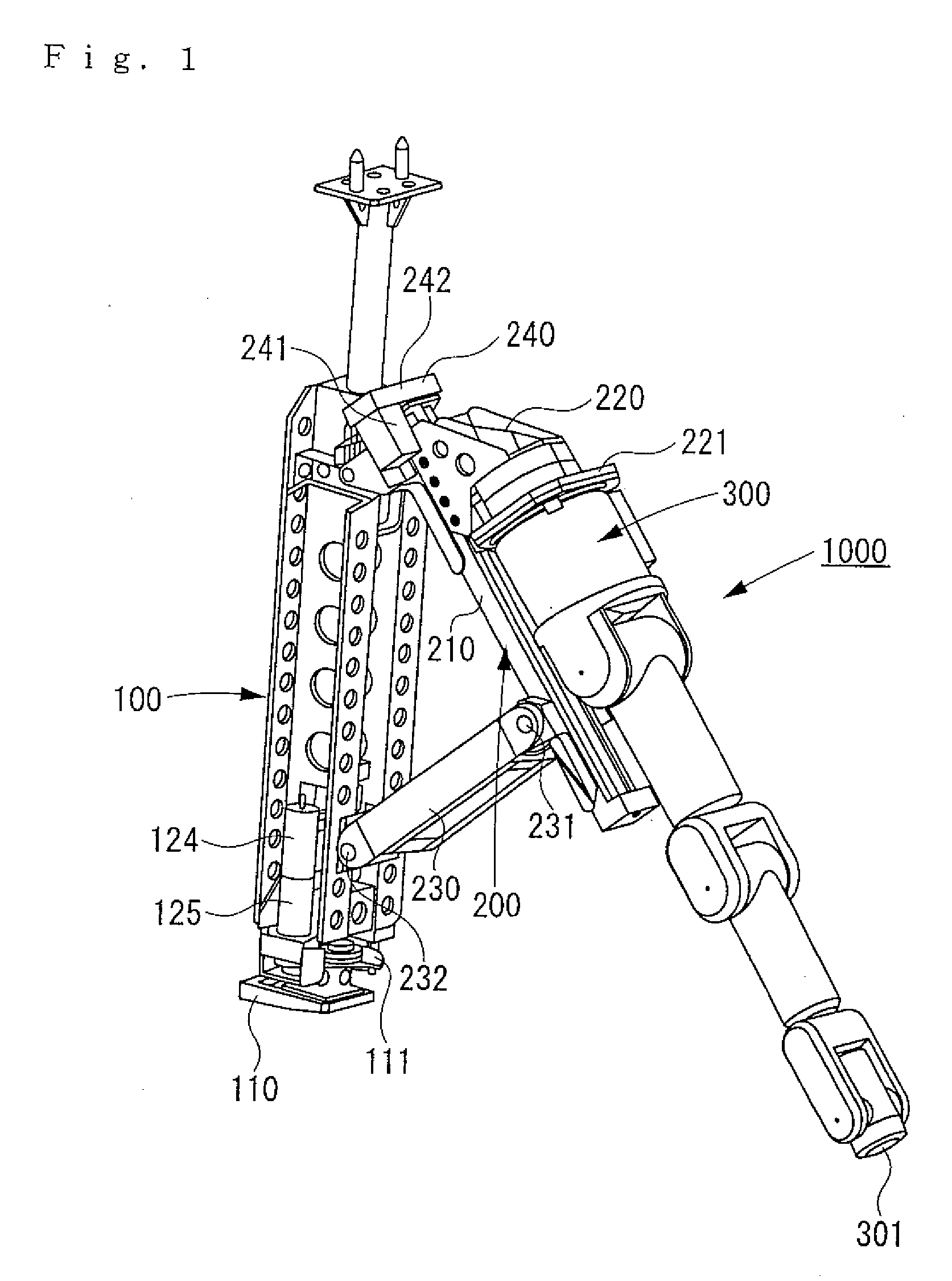
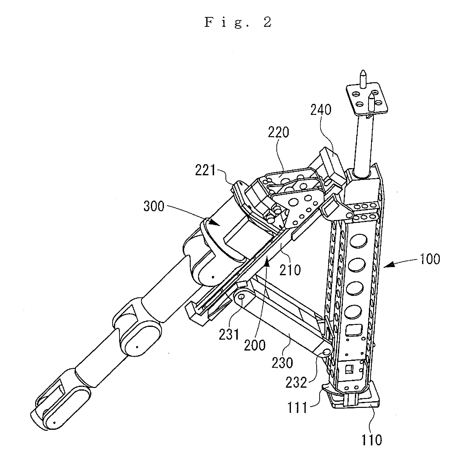
[0085]A tip tool guide apparatus 1000 according to Embodiment 1 of the present invention will be described with reference to FIGS. 1 and 2 which are perspective views, FIG. 3 which is a plan view, and FIG. 4 which is a sectional view taken along line A-A in FIG. 3.

[0086]The tip tool guide apparatus 1000 is composed of a swivel support portion 100, a slide table 200, and a manipulator 300 as main members. FIGS. 1 to 4 show a state in which the swivel support portion 100, the slide table 200, and the manipulator 300 are combined to constitute the tip tool guide apparatus 1000.

[0087]However, when this tip tool guide apparatus 1000 is to be brought into a water chamber of a steam generator, the swivel support portion 100, the slide table 200, and the manipulator 300 are separated from each other, and individually brought into the water chamber. The swivel support portion 100, the slide table 200, and the manipulator 300, which have been sequentially brought into the water ...

embodiment 2

[Embodiment 2]

[0133]Next, the procedure for bringing the above-described tip tool guide apparatus 1000 into the water chamber will be explained as Embodiment 2.

[0134]As shown in FIGS. 8 and 9, a carry-in rail device 500 is attached to the manhole H. The carry-in rail device 500 includes a rail 501, a pan / tilt mechanism 502, a trolley 503, a windup winch 504, a sheave 505, and a wire 506.

[0135]The pan / tilt mechanism 502 is fixed to the manhole H, and supports the rail 501 to be capable of panning (in a right-and-left direction) and tilting (in an up-and-down direction). The rail 501 is inserted from outside the water chamber 3b into the interior of the water chamber 3b obliquely upwardly.

[0136]The trolley 503 can move along the rail 501, and holds an upper part of the swivel support portion 100 in a pinned state. The wire 506 is paid off from the windup winch 504, passed over the sheave 505 installed at the leading end of the rail 501, then reversed, and connected to the trolley 503....

embodiment 3

[Embodiment 3]

[0158]Next, another procedure for bringing the above-mentioned tip tool guide apparatus 1000 into the water chamber will be explained as Embodiment 3.

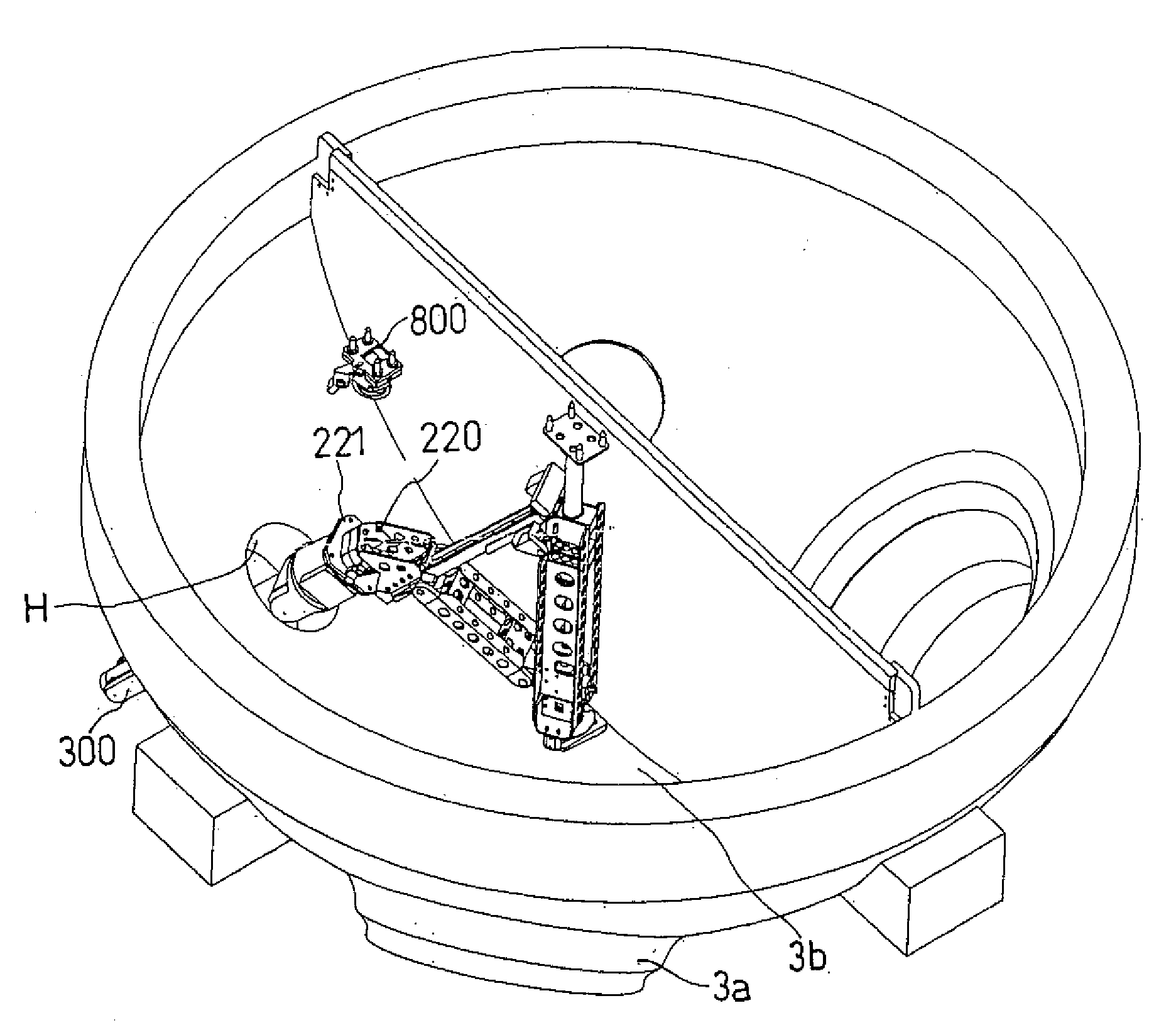
[0159]As shown in FIG. 28, a sheave device 800 is fixed to the ceiling surface of the water chamber 3b. This fixing is performed by inserting pins 801 of the sheave device 800 into the heat transfer tubes, and opening the pins 801 toward the outer periphery side (inflating the pins 801). A wire 803 is passed over a sheave 802 of the sheave device 800.

[0160]The leading end of the wire 803 is tied to the leading end of the swivel support portion 100, and the trailing end of the wire 803 is withdrawn out of the water chamber 3b through the manhole H. The trailing end side of the wire 803 is pulled by a winch or the like (not shown), whereby the swivel support portion 160 is brought into the water chamber 3b.

[0161]As shown in FIG. 29, the swivel support portion 100 brought into the water chamber 3b is self-supported and fixe...


PUM

PropertyMeasurementUnit
diameteraaaaaaaaaa
pressureaaaaaaaaaa
temperatureaaaaaaaaaa

Abstract

A tip tool guide apparatus is brought into a water chamber of a steam generator of nuclear power equipment, and guides a tip tool, such as a shot peening head, along a necessary region. For this purpose, a tip tool guide apparatus 1000 is composed of a swivel support portion 100, a slide table 200, and a manipulator 300. The swivel support portion 100 is self-supported and fixed within the water chamber, and turns the slide table 200 connected thereto. The slide table 200 connects the manipulator 300, and moves the manipulator 300 slidingly in a fore-and-aft direction. The manipulator 300 grasps the tip tool at its leading end. For bringing into the water chamber, the swivel support portion 100, the slide table 200, and the manipulator 300 are separated from each other, brought in individually, and assembled within the water chamber to constitute the tip tool guide apparatus 1000.

Description

BACKGROUND OF THE INVENTION[0001]1. Field of the Invention[0002]This invention relates to a tip tool guide apparatus, and a method for bringing in the tip tool guide apparatus.[0003]The tip tool guide apparatus of the present invention is an apparatus which is brought into a water chamber of a steam generator of nuclear power equipment, and guides various tip tools, necessary to perform shot peening, along a necessary processing region.[0004]The method for bringing in the tip tool guide apparatus according to the present invention is a method for efficiently bringing the tip tools into and out of the water chamber of the steam generator of nuclear power equipment via a manhole formed in the water chamber.[0005]2. Description of the Related Art[0006]FIG. 39 shows a primary system of pressurized light water reactor nuclear power equipment. As shown in this drawing, a reactor vessel 1, a pressurizer 2, a steam generator 3, and a pump 4 are sequentially connected by a main coolant pipe ...

Claims


Application Information

Patent Timeline
Patent Type & Authority Applications(United States)
IPC IPC(8): B21D37/00
CPCF22B37/005
Inventor MORI, NORIMASAONITSUKA, HIRONORIFUJITA, JUNOHTA, TAKAHIRONAGURA, YASUMITUKAMOTO, YOSHIMASANAKAJIMA, OSAFUMI
Owner MITSUBISHI HEAVY IND LTD
Why Eureka
Try Eureka