Heat exchanger

Inactive Publication Date: 2008-09-18
KEIHIN THERMAL TECH CORP
View PDF3 Cites 20 Cited by
  • Summary
  • Abstract
  • Description
  • Claims
  • Application Information

AI Technical Summary

Benefits of technology

[0028]According to the heat exchanger of par. 6), the above-described effect of the heat exchanger of any of pars. 2) to 5) is further enhanced.
[0029]According to the heat exchanger of par. 7), a plurality of bulging portions are formed on a portion of the partition plate present within a header section in which refrigerant flows into the heat exchange tubes such that the bulging portions project toward the heat exchange tubes and each have a flat projecting end wall; and at least one bulging portion includes a through hole formed in the projecting end wall. Therefore, by the action of the bulging portions, it becomes possible to control the divided flow of refrigerant from the heat-exchange-tube-side space of the header section to all the heat exchange tubes communicating with the header section such that the discharged-air temperature, or the temperature of air having passed through the heat exchanger, becomes uniform among different portions of the heat exchanger.
[0030]According to the heat exchanger of par. 8), the above-described effect of the heat exchanger of par. 7) is further enhanced.
[0031]According to the heat exchanger of par. 9), a plurality of hemispherical bulging portions are formed on a portion of the partition plate present within a header section in which refrigerant flows into the heat exchange tubes such that the bulging portions project toward the heat exchange tubes; and at least one bulging portion includes a plurality of through holes formed therein. Therefore, by the action of the

Problems solved by technology

In addition, since the through holes are formed by performing press working on the partition plate, it is impossible to form flanges around the through holes such that

Method used


Image

  • Heat exchanger
  • Heat exchanger
  • Heat exchanger

Examples


Embodiment Construction

[0053]An embodiment of the present invention will next be described in detail with reference to the drawings. The embodiment is of a heat exchanger according to the present invention that is applied to an evaporator of a car air conditioner using a chlorofluorocarbon-based refrigerant.

[0054]In the following description, the term “aluminum” includes aluminum alloys in addition to pure aluminum.

[0055]Further, the same reference numerals are used throughout the drawings to refer to similar parts or elements, and their repeated descriptions are omitted.

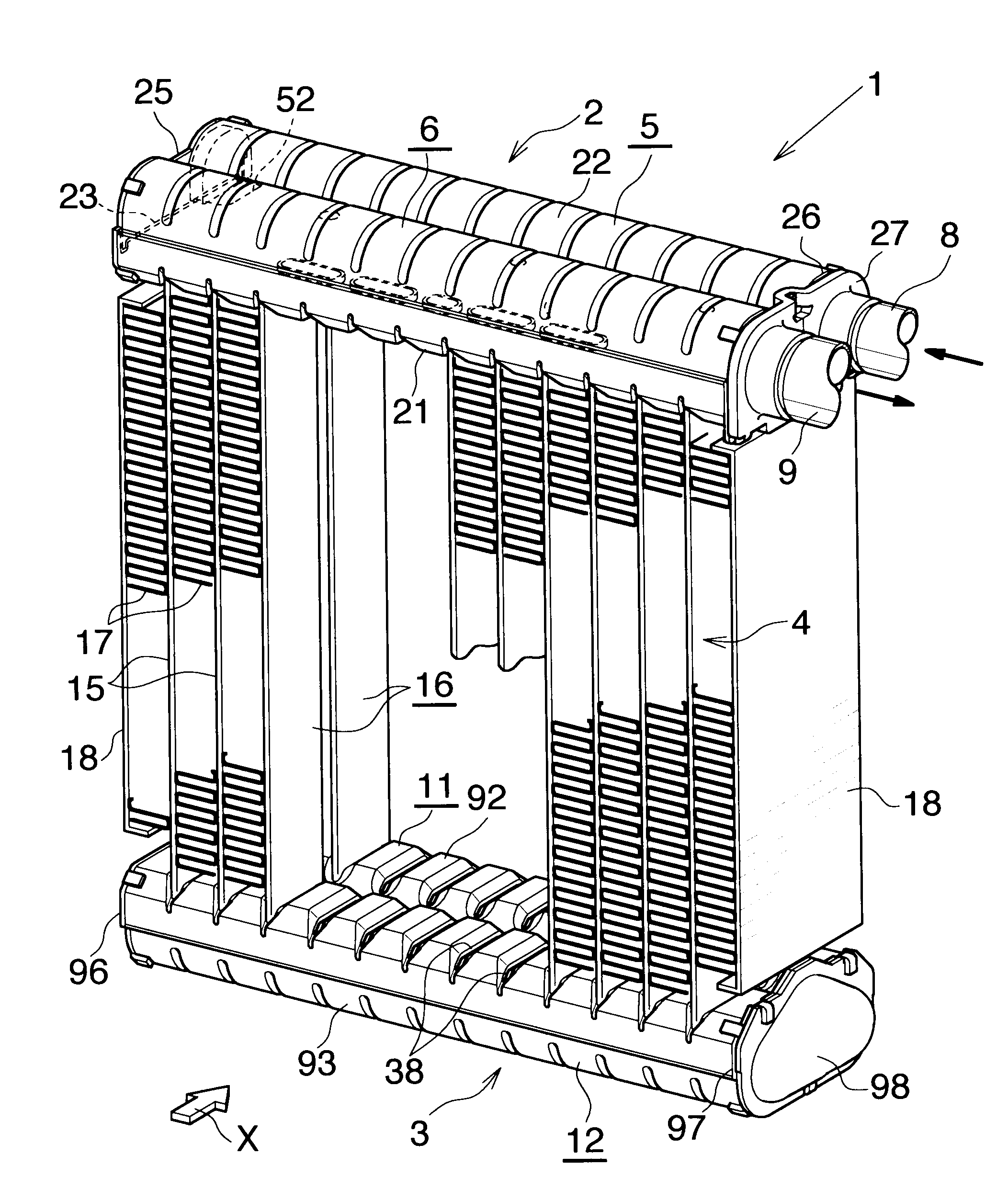
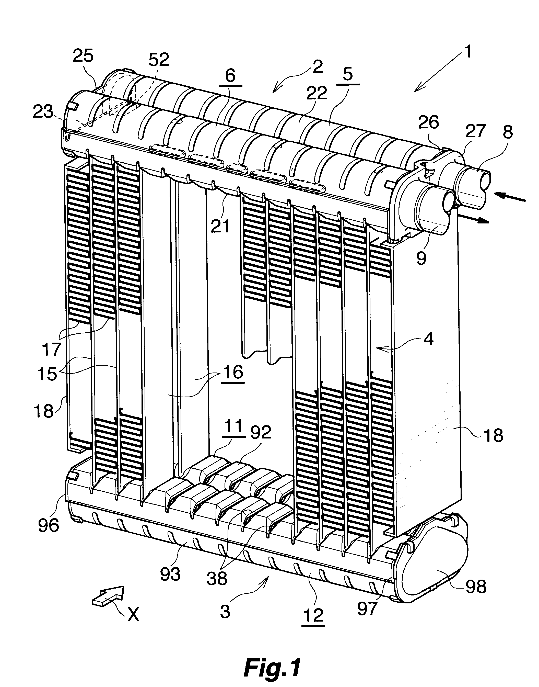
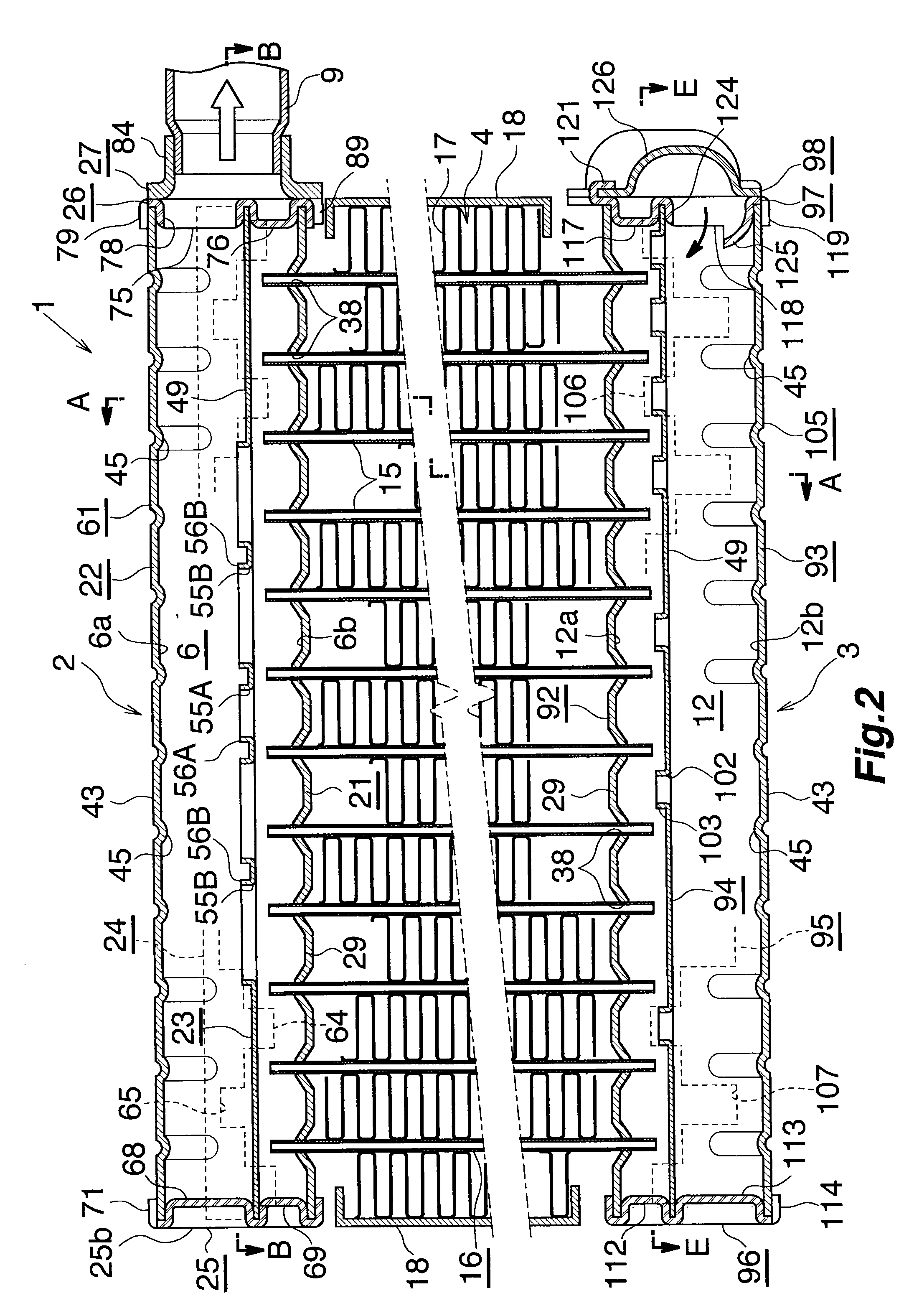
[0056]FIGS. 1 and 2 show the overall configuration of an evaporator, and FIGS. 3 to 9 show the configuration of a main portion of the evaporator.

[0057]As shown in FIGS. 1 to 3, the evaporator (1) is configured such that a heat exchange core section (4) is provided between a refrigerant inlet / outlet header tank (2) made of aluminum and a refrigerant turn header tank (3) made of aluminum, which are separated from each other in the vertical ...


PUM


Abstract

A heat exchanger used as an evaporator is configured such that two heat exchange tube groups, each composed of a plurality of heat exchange tubes, are provided between a pair of header tanks, while being separated from each other in a front-rear direction. Each of the header tanks includes two header sections. Each header tank includes a first member to which the heat exchange tubes are connected, a second member which is joined to the first member and covers the side of the first member opposite the heat exchange tubes, and a partition plate disposed between the first and second members and having partition portions which divide the interiors of the two header sections into respective upper and lower spaces. Through holes are formed in the partition portions so as to establish communication between the upper and lower spaces of the header sections.

Description

BACKGROUND OF THE INVENTION[0001]The present invention relates to a heat exchanger preferably used as an evaporator of a car air conditioner, which is a refrigeration cycle to be mounted on, for example, an automobile.[0002]Herein and in the appended claims, the upper, lower, left-hand, and right-hand sides of FIG. 2 will be referred to as “upper,”“lower,”“left,” and “right,” respectively. Also, herein and in the appended claims, the downstream side (a direction represented by arrow X in FIGS. 1 and 3) of an air flow through air-passing clearances between adjacent heat exchange tubes will be referred to as the “front,” and the opposite side as the “rear.”[0003]The applicant of the present application has proposed an improved heat exchanger as an evaporator for a car air conditioner which satisfies the needs of reducing size and weight and enhancing performance (see Japanese Patent Application Laid-Open (kokai) No. 2006-183994). In the improved heat exchanger, a plurality of heat exc...

Claims


Application Information

Patent Timeline
IPC IPC(8): F28D7/00
CPCF28D1/05391F28F9/0278F28F9/0204F28D2021/0071
Inventor HIGASHIYAMA, NAOHISATSURUMI, YUKIHIRO
Owner KEIHIN THERMAL TECH CORP
Why Eureka
Try Eureka