Joining of advanced materials by plastic deformation

a technology of advanced materials and plastics, applied in the field of joining together single-phase or multi-phase objects, can solve the problems of shrinkage of the construction, final machining of the construction, and the general difficulty of the construction to form into complex shapes, and achieve the effects of reliable joints, same porosity, transparency and strength

Inactive Publication Date: 2010-05-25
UCHICAGO ARGONNE LLC
View PDF3 Cites 3 Cited by
  • Summary
  • Abstract
  • Description
  • Claims
  • Application Information

AI Technical Summary

Benefits of technology

[0031]An object of the present invention is to provide a method for producing a structure which utilizes residual stresses to confer superior mechanical properties. A feature of the invention is utilizing high temperature plastic joining and predetermined positioning of subunits of the structure. An advantage of the invention is that material strength and toughness with the imposition of a single temperature and single pressure value during processing. These improvements in physical toughness occur in situ which is to say while the construct is being formed, and not after the construct is formed. Once the construct is cooled down from the high processing temperatures, the construct undergoes no further physical changes. As such, no post-fabrication “tempering” of the construct is required.
[0032]Yet another object of the present invention is to provide a method for joining subunits such that the resulting construct has optical transparency throughout its entire volume.
[0033]Still another object of the present invention is to provide a method for producing constructs exhibiting targeted compressive surface stresses. A feature of the invention is controlled particle sizing of the constituents of the subunits, a predetermined stacking order of the subunits, and an application of predetermined temperatures and compressive forces to the construct. An advantage of the invention is the production of reliable joints between the construct having the same porosity, transparency and strength as the subunits, all without the need for a joint compound intermediate the subunits.
[0034]In brief, the invention provides a method for the fabrication of constructs containing preselected regions of residual stress, the method comprising selecting constituents of the construct which exhibit grain boundary sliding at temperatures below 0.7 times the melting point temperature of the lowest melting point constituent; assem-bling the constituents to form a loosely assembled construct, and wherein a first subunit with a first coefficient of thermal expansion contacts a second subunit with a second coefficient of thermal expansion; and compressing the loosely assembled construct for a time and at a temperature to cause grain boundary sliding between constituents comprising the first and second subunits to form a rigid construct. The subunits can be similar or dissimilar in constituency, and can be single or multi-phase materials. In an embodiment, the subunits are selected based on their having certain regions of residual stress such that the final construct will exhibit preselected regions of residual stress.
[0035]The invention provides a construct comprising a first crystalline solid having a first surface directly bonded to a second surface of a second crystalline solid, wherein the finish of the first surface and second surface are less than or equal to two microns (equivalent to a diamond-saw cut surface), as defined by standard root-mean-square values.
[0036]The invention also provides a method for the fabrication of constructs whereby the resulting constructs exhibit tailored regions of residual stress, the method comprising selecting constituents of the construct which exhibit grain boundary sliding at temperatures below 70 percent of the melting point (0.7TM) of the lowest melting point constituent; assembling the constituents to form a loosely assembled construct, and wherein a first subunit with a first coefficient of thermal expansion contacts a second subunit with a second coefficient of thermal expansion; and compressing the loosely assembled construct for a time and at a temperature to cause grain boundary sliding between constituents comprising the first and second subunits to form a rigid construct.

Problems solved by technology

Ceramics in general are difficult to form into complex shapes.
This heat application will result in shrinkage of the construct and therefore final machining of the construct.
This can be difficult and costly.
This method also can be difficult, time consuming, expensive, and can introduce flaws in the structure.
Flaws introduce stress concentrations which reduce performance of the structure and otherwise render the shape unusable.
However, the resulting joints have poor mechanical properties compared to the materials to be joined, and the application temperatures are limited.
However, nanocrystalline materials can be very expensive and can be difficult to work with.
Nanocrystalline ceramics are difficult to consolidate into a dense body without having the individual grains grow substantially.
For example, such powders tend to agglomerate badly, hence making it difficult to produce dense bodies or to apply materials uniformly to a surface.
Also, nanocrystalline powders are often highly hygroscopic.
Adsorption of moisture can make it difficult or impossible to process nanocrystalline ceramic powders into strong, pore-free bodies.
These pores grow and eventually join to form cracks which reduce the ceramic strength.
In these and other similar instances, the interlayer was difficult to prepare and therefore an expensive feature.
With respect to joining simple cermets to form more complex structures, such as, for example, serrated cutting edges, no joining technology has been found to be widely successful.
Conventional welding is ineffective because, at welding temperatures, the ceramic is solid but the metallic phase is liquid.
Leaching of the metal and destruction of the cermet occurs during welding.
Conventional brazing or soldering forms joints with insufficient strength for many applications.
Also, the resulting joints have poor resistance to heat.
Because cutting and grinding operations often produce substantial heating of the cermet tooling, and the stresses on the tooling are high, brazed or soldered joints will fail in most applications.
The required procedures make use of intricate and relatively expensive dies or diamond-tooling machining.
Furthermore, because of geometric constraints associated with part removal from a die, the shapes that can be formed are limited.
All of the above produce a joint with inferior strength and properties different from the bulk material being joined.

Method used


Image

  • Joining of advanced materials by plastic deformation
  • Joining of advanced materials by plastic deformation
  • Joining of advanced materials by plastic deformation

Examples


example 1

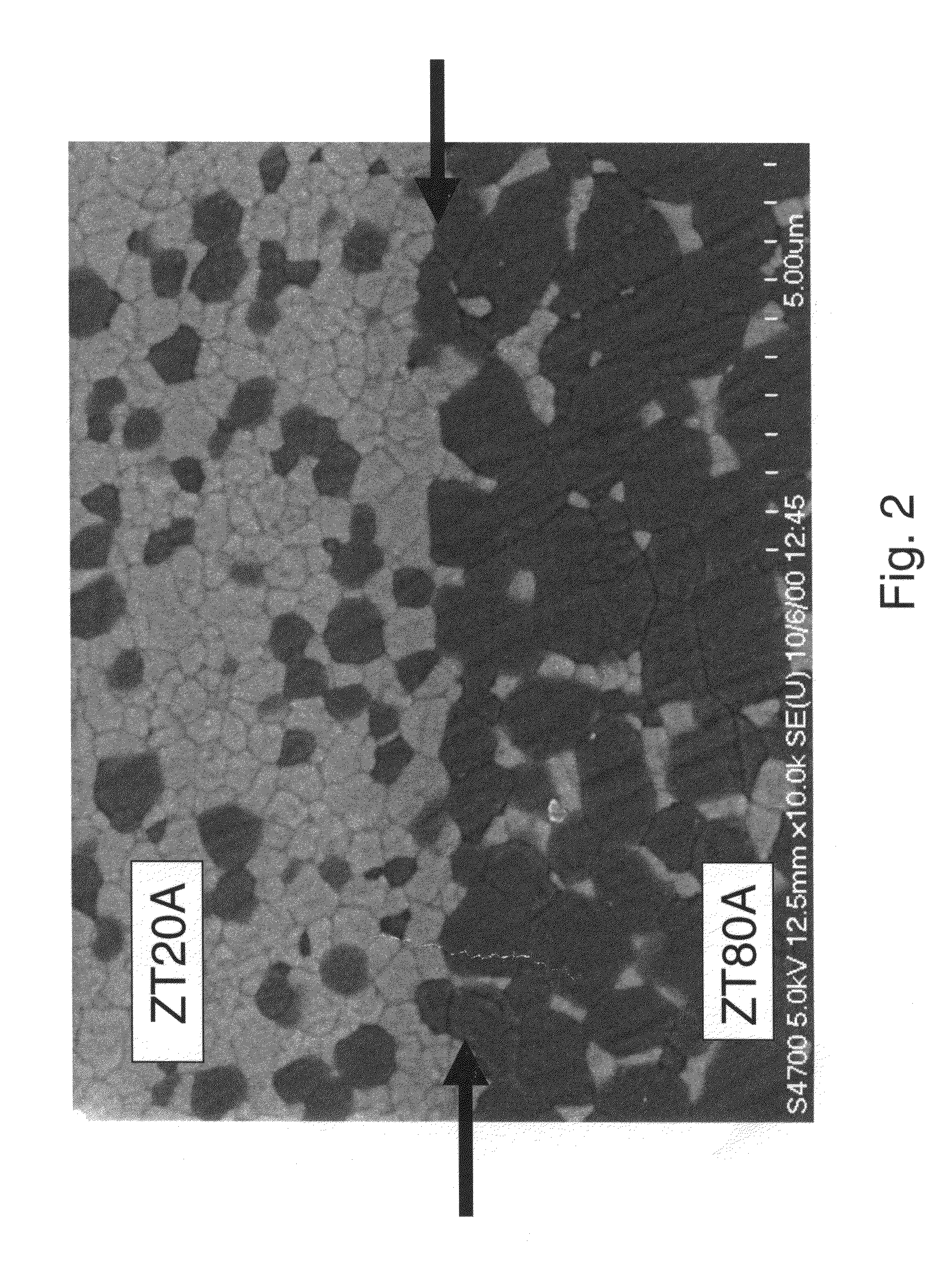
[0097]Dense Al2O3 / YSZ pellets, denoted ZTA, are joined without an intermediate layer. The invented protocol allows for one of the pellets to be from 15 to 85% Al2O3, with the balance being YSZ, and the other pellet being from 0 to 100% Al2O3, with the balance being YSZ. The pellets are prepared by blending starting powders well in the case of particulate ZTA composites or simply weighing out powders in the case of monolithic ceramics. The powders are then cold-pressed into compadts, which are sintered in air, oxygen, or inert atmosphere at temperatures of 1400-1600° C.

[0098]Thermal-expansion coefficients of the ceramics and composites were measured in a Theta Industries Dilatronic (Port Washington, N.Y.).

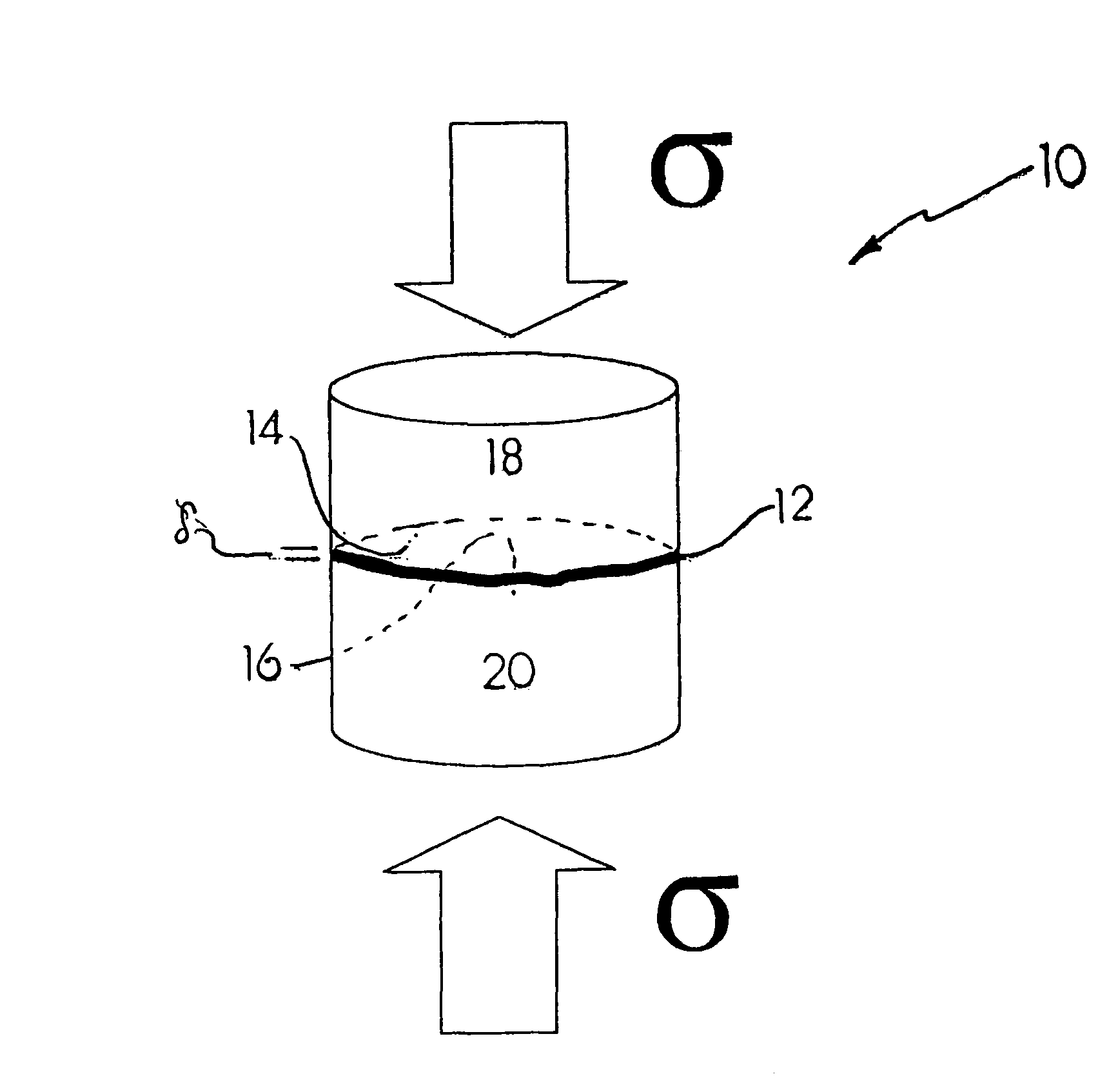
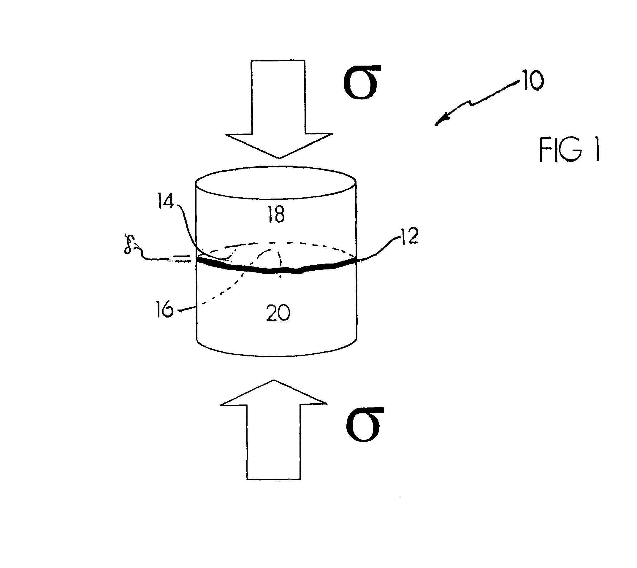
[0099]Once the two surfaces are mated, the construct is placed under compression utilizing a commercially available ram, such as an Instron universal testing apparatus (Canton, Mass.). The construct and compression rams are then heated to a temperature that is approximately 0.6 that...

example 2

[0102]If an intermediate joint compound is used, the dense bodies to be joined can be, but are not limited to, ZTA composites, or pure Al2O3, or pure ZrO2. They are prepared in the same manner as described in Example 1. Once they have been sintered, they are coated with the joint material.

[0103]In this example, a dense 60 vol. % Al2O3 / 40 vol. % YSZ body is joined to a dense 40 vol. % Al2O3 / 60 vol. % YSZ body. The intermediate layer is 50 vol. % Al2O3 / 50 vol. % YSZ (50ZTA), which is applied by aerosol spraying. No surface preparation is required of the bodies to be joined. The joint material is prepared by blending 2 g of 50ZTA, 5 g of solvent, 1.2 g a suitable binder, such as of Rohm & Haas AT-51 binder, 0.15 g of a plasticizer such as 0.15 g of Monsanto S-160 plasticizer, and 0.06 g dispersant, such as Avecia S-9000 dispersant. These constituents are placed in a milling container, in this case a 25 mL polyethylene jar, along with YSZ grinding media. The jar was then sealed and plac...

example 3

Join Optical Ceramics:

[0130]Applications for such materials include optical windows, wave guides, fibers, radomes, and mirrors. MgF2 is perhaps the most widely used ceramic for optical applications. It transmits IR wavelengths (0.2-10 μm), but our process can be used to join other polycrystalline optical-transmitting materials based on oxides, halides, and silicates.

[0131]In one embodiment: MgF2 ceramics of sample size 3×3×5 mm were mated, with no surface preparation. They were heated in argon to 800° C. and compressed at strain rates of 5×10⁻⁶ / s to a total strain of less than 5%. Optical transmission properties of as-received and joined samples were measured and found to be almost identical.


PUM

PropertyMeasurementUnit
average sizeaaaaaaaaaa
pressureaaaaaaaaaa
grain sizesaaaaaaaaaa

Abstract

A method for utilizing plastic deformation resulting from grain boundary sliding with or without a novel joint compound that leads to the joining of advanced ceramic materials, intermetallics, and cermets. A joint formed by this approach is as strong as or stronger than the materials joined. The method does not require elaborate surface preparation or application techniques. The method also allows for the formation of transparent joints between two subunits of a construct joined via plastic deformation. The method can be used to tailor residual stresses and maintain native porosity.

Description

[0001]This utility patent application claims the benefit of U.S. Provisional Application No. 60 / 749,844, filed on Dec. 12, 2005. This utility patent application is a Continuation-in-Part of U.S. patent application Ser. No. 11 / 302,419, filed Dec. 12, 2005 now U.S. Pat. No. 7,413,109, which is a Divisional of U.S. patent application Ser. No. 09 / 924,571, filed Aug. 7, 2001, and issued on Dec. 13, 2005 as U.S. Pat. No. 6,974,070.CONTRACTUAL ORIGIN OF THE INVENTION[0002]The United States Government has rights in this invention pursuant to Contract No. W-31-109-ENG-38 between the United States Government and The University of Chicago and / or pursuant to Contract No. DE-AC02-06CH11357 between the United States Government and UChicago Argonne, LLC representing Argonne National Laboratory.BACKGROUND OF THE INVENTION[0003]1. Field of the Invention.[0004]The present invention relates to a method for joining together single-phase or multi-phase objects and similar and dissimilar objects, and mor...

Claims


Application Information

Patent Timeline
Patent Type & Authority Patents(United States)
IPC IPC(8): C03B29/00B29C65/00B31B1/60B32B37/00
CPCC04B35/645C04B37/005C04B37/026C04B37/001Y10T156/10C04B2237/064C04B2237/068C04B2237/121C04B2237/122C04B2237/123C04B2237/34C04B2237/343C04B2237/348C04B2237/36C04B2237/402C04B2237/405C04B2237/58
Inventor ROUTBORT, JULES L.SINGH, DILEEPGORETTA, KENNETH C.GUTIERREZ-MORA, FELIPE
Owner UCHICAGO ARGONNE LLC
Why Eureka
Try Eureka